Functions
2.1 General
SIPROTEC, 7SD610, Manual
C53000-G1176-C145-6, Release date 02.2011
37
Current transformer 10P10; 30 VA → n=10; P
N
=30VA
Current transformer 10P20; 20 VA → n=20; P
N
=20VA
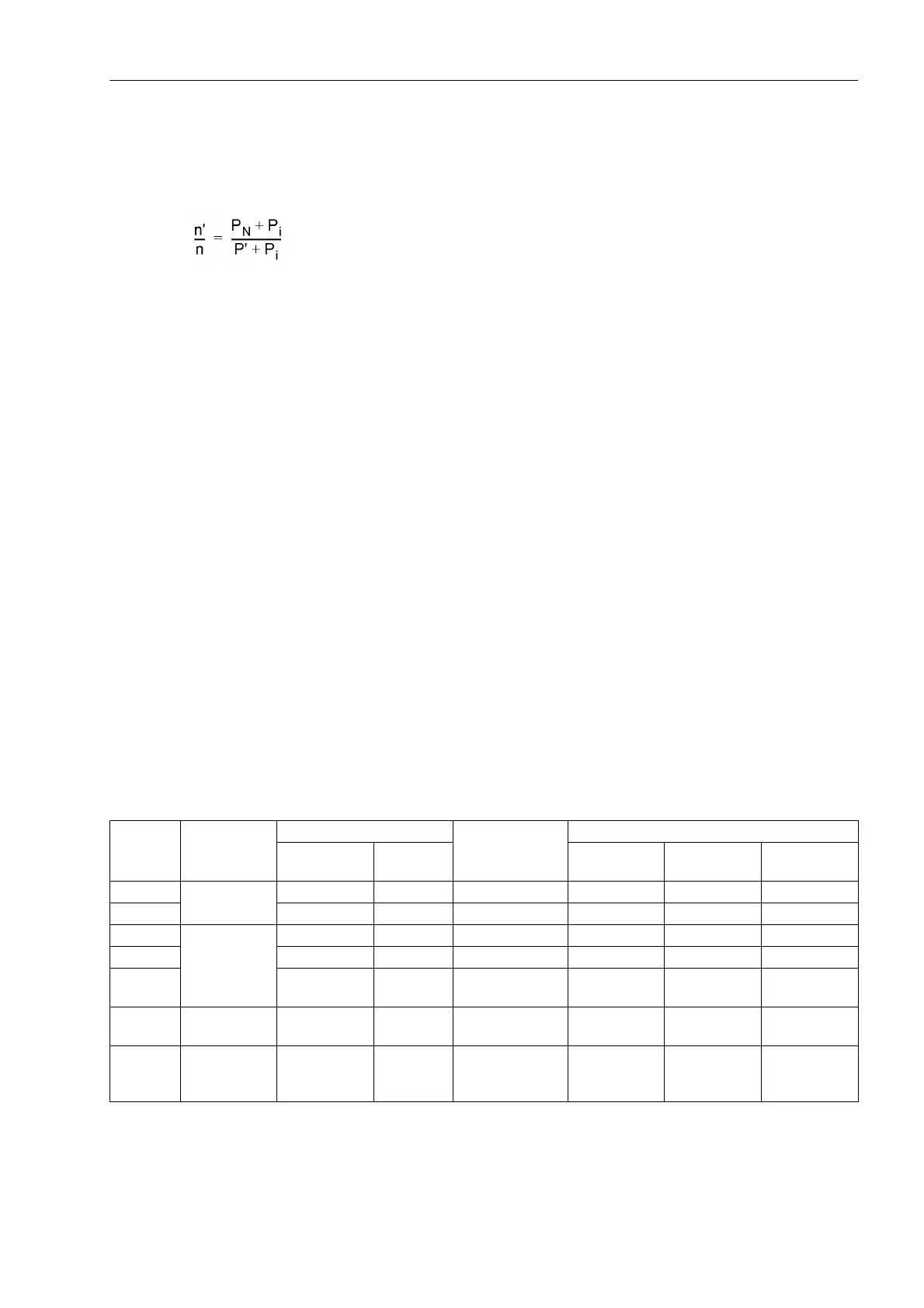
The operational accuracy limit factor n' is derived from these rated data and the actual secondary burden P':
With
n' = operational accuracy limit factor (effective overcurrent factor)
n = rated accuracy limit factor of the current transformers (distinctive number behind P)
P
N
= rated burden of the current transformers [VA] at rated current
P
i
= internal burden of the current transformers [VA] at rated current
P' = actually connected burden (devices + secondary lines) [VA] at rated current
Usually, the internal burden of the current transformers is stated in the test report. If it is unknown, it can be
roughly calculated from the DC resistance R
i
of the secondary winding.
P
i
≈ R
i
· I
N
2
The ratio between operational accuracy limit factor and rated accuracy limit factor n'/n is set at address 251
K_ALF/K_ALF_N.
The CT error at rated current, plus a safety margin, is set at address 253 E% ALF/ALF_N. It is equal to the
„current measuring deviation for primary nominal current intensity F1“ according to VDE 0414 / Part 1 or IEC
60044. It is
– 3 % for a 5P transformer,
– 5 % for a 10P transformer.
The CT error at rated accuracy limit factor, plus a safety margin, is set at address 254 E% K_ALF_N. It is
derived from the number preceding the P of the transformer data.
Table 2-1 illustrates some usual protective current transformer types with their characteristic data and the rec-
ommended settings.
Table 2-1 Recommended settings for current transformer data
1)
If n'/n ≤ 1.50, setting = calculated ratio; if n'/n > 1.50, setting = 1.50
CT class Standard Error at rated current Error at rated
accuracy limit
factor
Recommended settings
Transforma-
tion ratio
Angle Address 251 Address 253 Address 254
5P IEC 60044-1 1,0 % ± 60 min ≤ 5% ≤ 1,50
1)
3,0 % 10,0 %
10P 3,0 % — ≤ 10 % ≤ 1,50
1)
5,0 % 15,0 %
TPX IEC 60044-1 0,5 % ± 30 min ε ≤ 10 % ≤ 1,50
1)
1,0 % 15,0 %
TPY 1,0 % ± 30 min ε ≤ 10 % ≤ 1,50
1)
3,0 % 15,0 %
TPZ 1,0 % ± 180 min
± 18 min
ε ≤ 10 %
(only I∼)
≤ 1,50
1)
6,0 % 20,0 %
PX IEC 60044-1
BS: Class X
≤ 1,50
1)
3,0 % 10,0 %
C100
to
C800
ANSI ≤ 1,50
1)
5,0 % 15,0 %

 Loading...


