Functions
2.5 Restricted Earth Fault Protection (optional)
SIPROTEC, 7SD610, Manual
C53000-G1176-C145-6, Release date 02.2011
84
Evaluation of Measurement Quantities
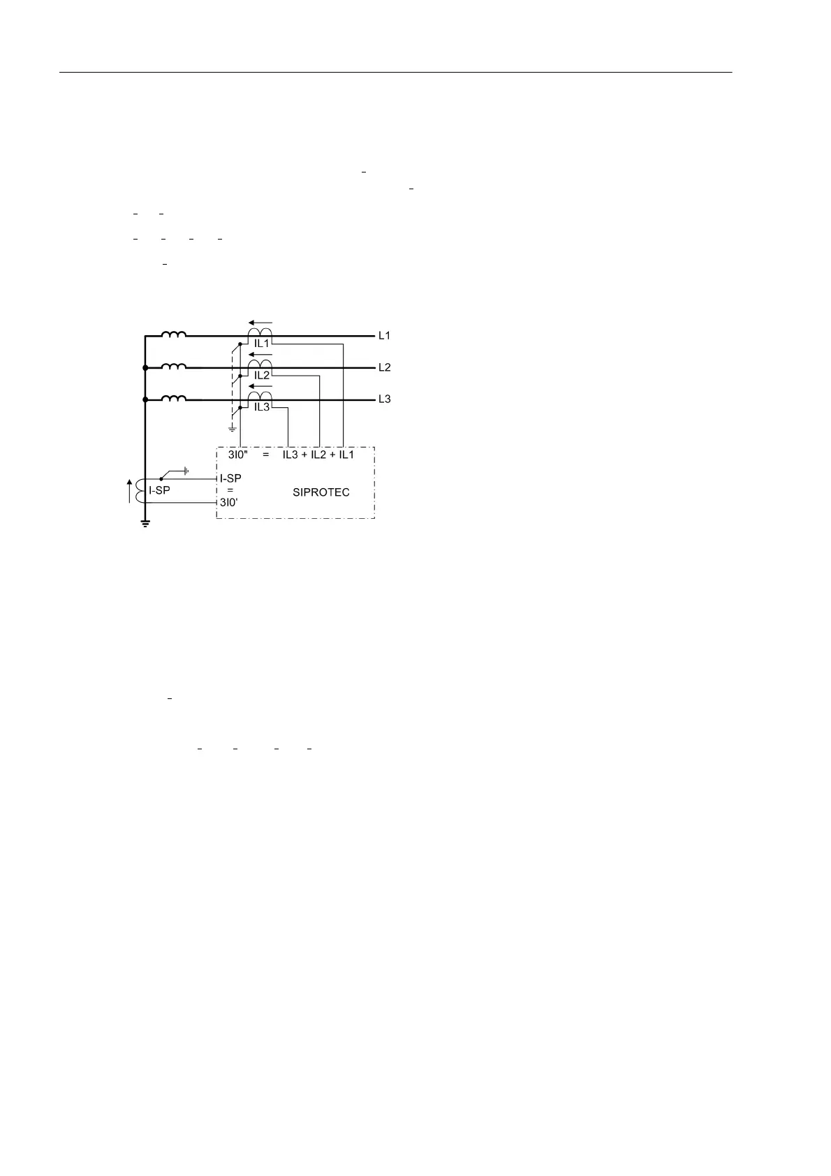
The earth fault differential protection compares the fundamental component of the current flowing in the star-
point connection, which is designated as 3I
0
' in the following, with the fundamental component of the sum of
the phase currents designated in the following as 3I
0
”. Thus, the following applies (Figure 2-29):
3I
0
' = I
SP
3I
0
" = I
L1
+ I
L2
+ I
L3
Only 3I
0
' acts as the tripping effect quantity. During a fault within the protected zone this current is always
present.
Figure 2-29 Principle of restricted earth fault protection
When an earth fault occurs outside the protected zone, a zero sequence current also flows though the phase
current transformers. This is, on the primary side, in counter-phase with the starpoint current and has equal
magnitude. Therefore, both the magnitude of the currents and their phase relationship are evaluated for re-
straint purposes. The following is defined:
A tripping current
I
Ref
=|3I
0
'|
and a stabilisation or restraining current
I
Rest
= k · ( |3I
0
'–3I
0
"| – |3I
0
'+3I
0
"| )
where k is a stabilisation factor which will be explained below, at first we assume k = 1. I
REF
produces the trip-
ping effect quantity, I
Rest
counteracts this effect.
To illustrate the effect, have a look at the three important operating conditions with ideal and adapted measured
values:

 Loading...


