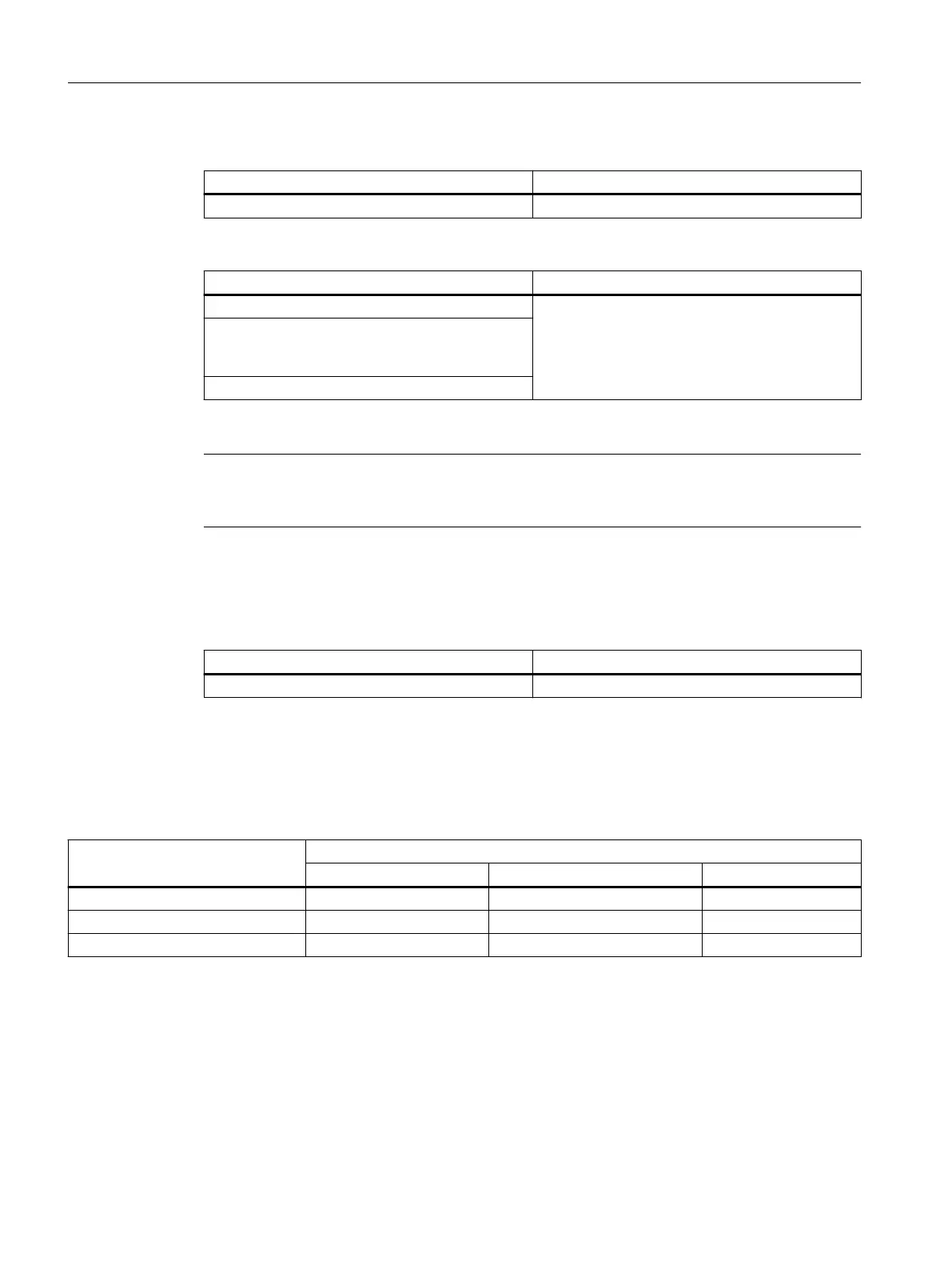
Motor starter protector + contactor + solid-state overload relay (size S3)
Thermal restrictions Mechanical restrictions
On request On request
Motor starter protector + contactor + thermal overload relay (size S00 / S0)
Thermal restrictions: Mechanical restrictions
Reduce permissible ambient temperature by 20 K DIN rail adapter required
No side-by-side mounting
(≥ 10 mm clearance for vertical installation,
> 20 mm for horizontal installation)
Current derating to 87 % of I
n
Motor starter protector + contactor + thermal overload relay (size S2 / S3)
Note
A three-part combination consisting of a motor starter protector, a contactor and a thermal
overload relay is not permissible for sizes S2 and S3.
Reference
More information ... Can be found in the chapter titled ...
About assembly kits for fuseless load feeders Accessories (Page 123)
Connection systems
Self-assembled fuseless load feeders are available with the following connection system options.
Table 3-5 Connection systems available for self-assembled fuseless load feeders
Connection system Self-assembled fuseless load feeders
S00 / S0 S2 S3
Screw terminals ✓ ✓ ✓
Spring-loaded connection ✓
2) 2)
Ring cable lug connection ✓
1)
— —
1)
These versions can be snapped onto a DIN rail. Mounting on a busbar adapter is not possible.
2)
In the case of size S2 and S3 devices, spring-loaded terminals are only possible in the auxiliary circuit.
Product description
3.2 Device versions
SIRIUS 3RA Load Feeders
20 Equipment Manual, 02/2022, A5E03656507520A/RS-AC/004

 Loading...


