Note
Contactor size S0 alternating current (AC)
S0 contactors with AC operation and spring-loaded connection system need a spacer (d) for DIN
rail or busbar adapter mounting.
Note
Reverse the above sequence to disassemble both sizes S00 and S0.
7.3 Assembly and disassembly with dierent mounting systems
Assembly/Installation
Fuseless load feeders can be mounted on the following assembly systems:
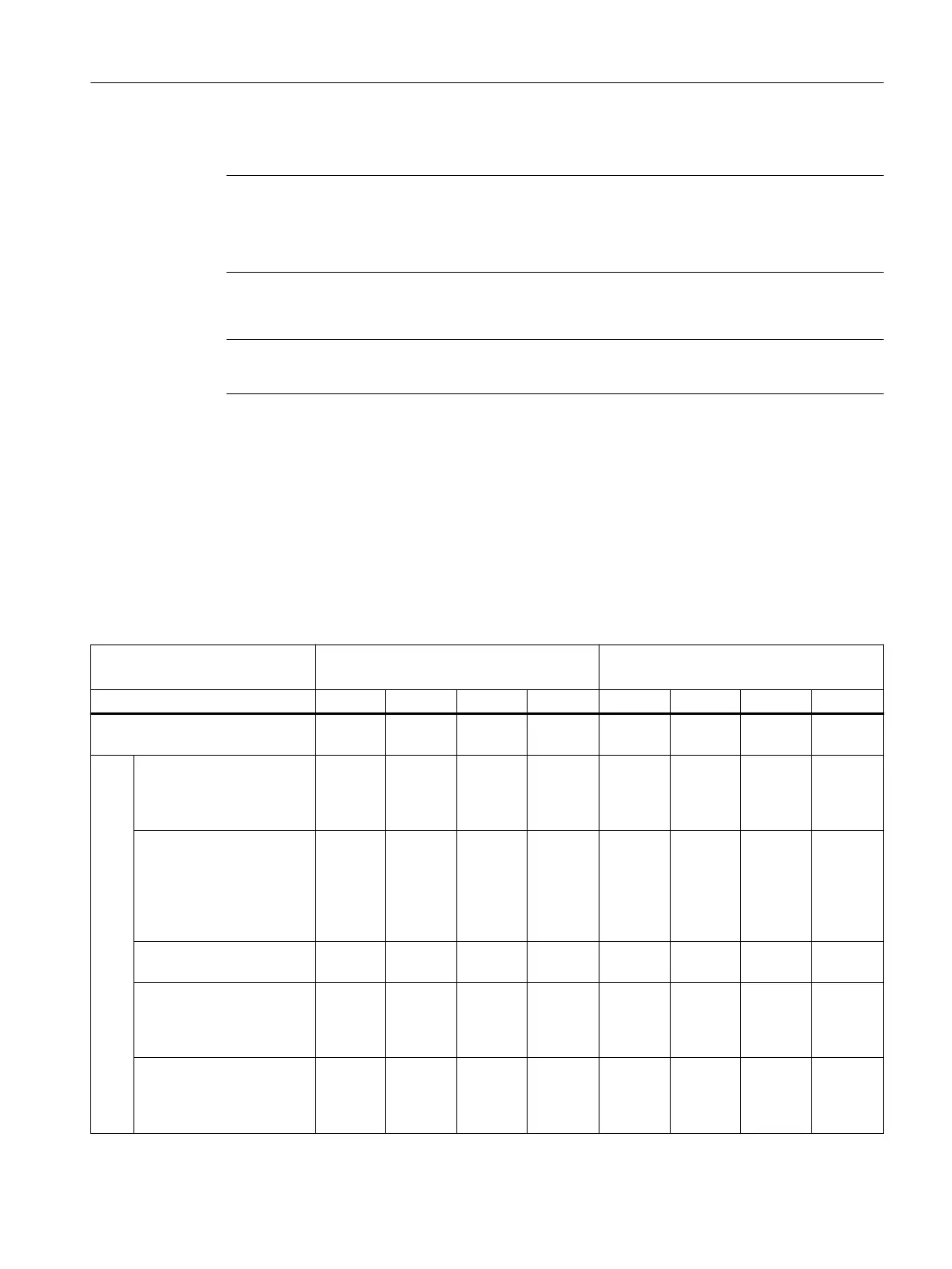
Table 7-5 Assembly systems
Starter combination Direct-on-line starter Reversing starter
Size S00 S0 S2 S3 S00 S0 S2 S3
Mounting on 35 mm DIN rail acc.
to DIN EN 60715
Snap-on mounting with‐
out adapter
✓
1)
✓
1)
✓
2)
(DIN rail
spacing
175 mm)
— ✓
1)
— — —
With 3RA2922-1BA00 DIN-
rail adapter
✓
1) 3)
(screw-
type con‐
nection
system
only)
✓
1) 3)
(screw-
type con‐
nection
system
only)
— — ✓
1) 3)
(screw-
type con‐
nection
system
only)
✓
1) 3)
(screw-
type con‐
nection
system
only)
— —
With 3RA2922-1AA00 DIN-
rail adapter
✓
1) 3)
✓
1) 3)
— — ✓
1) 3)
✓
1) 3)
— —
With 3RA2932-1AA00 DIN-
rail adapter
— — ✓
2)
(DIN rail
spacing
125 mm)
— — — ✓
2)
—
With 3RA2942-1AA00 DIN-
rail adapter
— — — ✓
2)
(DIN rail
spacing
125 mm)
— — — ✓
2)
(DIN rail
spacing
125 mm)
Mounting
7.3 Assembly and disassembly with dierent mounting systems
SIRIUS 3RA Load Feeders
Equipment Manual, 02/2022, A5E03656507520A/RS-AC/004 61

 Loading...


