Monitoring
Initialization
When the monitoring relay is connected to the supply voltage, the initialization phase starts and
internal functional tests are performed. During the initialization phase that lasts approximately
1.6 s, the connection to the 3UL23 residual-current transformer is one of the things that is
checked. During this time, no measurement or monitoring of the fault current takes place. - - A
is shown on the display. The relay switching behavior during the initialization phase can be
determined with the help of the "Init" parameter. In the factory setting ("Init" parameter = ERR),
the output relays switch to the fault state until completion of the initialization phase because
there is no valid measuring result of the fault current.
If the parameter is set to "OK", it is assumed that there is no internal fault and the fault current
will be within the set limits. For this reason, the output relays are switched to the work position
when the supply voltage is present.
This parameter setting is useful if the residual current monitoring relays are not permanently
connected to the supply voltage and instead are to be started immediately when the monitored
application is started, and output relays in the alarm position result in immediate shutdown of
the application again, e.g. when connecting a contactor with interruption of the self-locking by
the output relay contacts.
After completion of the initialization phase, a permanent self-test takes place without
interrupting the monitoring function.
Normal operation
If the measured fault current exceeds the set warning threshold (I!), the associated CO contact
21-22-24 changes the switching state without delay. On the display, the arrows for "threshold
overshot" and "measured value within the set limits" (
) ash alternately as an indication.
On the display, the currently displayed measuring value and the symbol for overshoot ash.
Note
Currents with line frequencies of between 16 and 400 Hz can be monitored by 3UG4625
residual current monitoring relays in conjunction with 3UL23 residual current transformers!
Startup delay
The set ON-delay time is triggered if the fault current overshoots the lower measuring range limit
of 20 mA (onDel). During this time, exceeding the set limit values will not trigger a relay response
of the CO contacts.
To start a drive, the output relay switches to the correct state during the ON-delay time (onDel),
depending on the selected open-circuit principle or closed-circuit principle, even if the measured
value remains above the set value.
Tripping delay
If the measured value exceeds the set threshold (I
▲
) after expiry of the ON-delay time (onDel),
the set tripping delay time (I
▲
Del) starts and the relay symbol ashes. After expiry of this time,
the output relay K1 changes the switching state. Exceeding the set warning threshold will cause
output relay K2 to switch immediately without taking into account the tripping delay time. On
the display, the actual measured value and the symbol for overshoot ash.
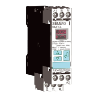
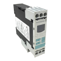
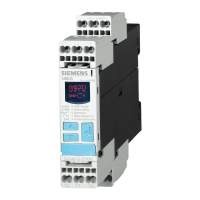
3UG4625 residual current monitoring relay with 3UL23 transformer
8.3 Functions
SIRIUS 3UG4 / 3RR2 monitoring relay
140 Equipment Manual, 07/2021, NEB927043002000/RS-AD/005
 Loading...

