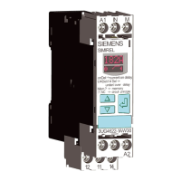
You will nd the switching states of the output relays below in section "Function diagrams" and
in Chapter "Diagnostics (Page 146)."
Tripping conditions
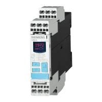
The combination of 3UG4625 residual current monitoring relay and 3UL23 residual current
transformer responds according to the following tripping conditions:
Residual current monitoring re‐
lays
Fault current
No tripping 0 to 85 % of the set threshold
Tripping not dened 85 to 100 % of the set threshold
Tripping >= 100 % of the set threshold
3UL23 residual current transformer
3UL23 residual current transformers can be used in conjunction with 3UG4625 residual current
monitoring relays to detect fault currents in machines and systems.
3UL23 residual current transformers are suitable for detecting pure AC fault currents and AC
fault currents with a pulsating direct-current component.
These necessary accessories are described in Chapter "3UL23 residual current transformers for
3UG4625 monitoring relays (Page 249)."
Note
Do not ground the neutral conductor downstream of the residual current transformer as
otherwise fault current monitoring functions can no longer be ensured.
Function diagrams for 3UG4625
Note
Dierence between Hyst and Hysteresis
In the following diagrams, the term "Hyst" refers to the "Hysteresis" parameter. The "Hysteresis"
parameter refers to the monitored limit values (I▲) and can be set in the SET menu.
However, "Hyst = 5 %" refers to the warning thresholds (I!) and is permanently set to 5 %.
3UG4625 residual current monitoring relay with 3UL23 transformer
8.3 Functions
SIRIUS 3UG4 / 3RR2 monitoring relay
Equipment Manual, 07/2021, NEB927043002000/RS-AD/005 141
 Loading...

