SITRANS P DS III
Service Manual, 06/2014, A5E34219855-01
19
Depending on a customer-specific order, the device comprises different parts.
Cable inlet, optionally with cable gland
Cover (front), optionally with inspection window
Cover (rear) for electrical terminal compartment
Electrical terminal compartment
Protective conductor connector/equipotential
Retaining screw; twist proofing of the measuring cell
in relation to the electronics enclosure
Nameplate (approval information)
Nameplate (general information)
Figure 3-1 View of the transmitter: Left: Front right: Rear view
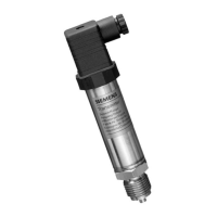
● The electronics enclosure is made of die cast aluminum or precision cast stainless steel.
● The housing has a removable circular cover at the front and the back.
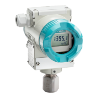
● Depending on the device version, the front cover
② may be designed as an inspection
window. You can read the measured values straight off the digital display through this
inspection window.
● The cable inlet
⑧ to the electrical terminal compartment is at the side; either the left or
right-hand one can be used. The unused opening is closed with a blanking plug
⑬.
● The protective conductor terminal/equipotential bonding terminal
⑪ is located at the back
of the enclosure.
 Loading...