Maintenance and servicing
5.7 Replacing parts
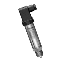
SITRANS P DS III
48 Service Manual, 06/2014, A5E34219855-01
6. Use a TX9 Torx screwdriver or Phillips screwdriver to unscrew the two screws of the
keyboard PCB you can now see from the base of the housing.
7. Remove the keyboard PCB.
1. Work in the reverse order as described in "Procedure for replacing the application
electronics".
2. When inserting the new application electronics, make sure that the contact pins fit in the
rear of the application electronics.
The ribbon cable of the measuring cell should be positioned between the contact pins,
and that of the keyboard PCB on the left of the pins.
3. Do not kink, pinch, tension or twist the ribbon cable when plugging it onto the application
electronics.
4. Close the device as described in Chapter Closing the device (Page 26).
5. Following a replacement, permanently obliterate the firmware ID on the nameplate if
applicable.
6. Write the new firmware ID on the nameplate.
7. Calibrate the zero point of the device, and also the span if necessary. Calibration of the
span is necessary if the device was matched e.g. to a control system prior to replacement
of the application electronics. Compare section Technical specifications (Page 55).
 Loading...