Procedure
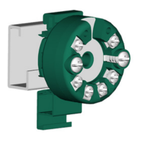
1. Place the springs on the xing screws.
2. Secure the lock washers.
① Fixing screw M4x35 ② Transmitter
③ Round plate ④ Lock washer DIN 6799 - 3.2 A2
Figure 4-1 Securing the lock washer
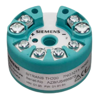
3. Secure the transmitter with the xing scr
ews in the connection head base.
① Transmitter
③ Connection head
Figure 4-2 Securing the transmitter in the connection head base
4.2.2 Ins
talling SITRANS TH100/320/420 in the raised cover of the connection head
Condition
The transmitter is only designed for installation in a type B connection head or larger.
Installing/mounting
4.2 Installing SITRANS TH100/320/420 in a connection head
SITRANS TH100/TH100Slim/TH320/TH420/TR320/TR420/TF320/TF420
32 Compact Operating Instructions, 07/2021, A5E41865021-AE

 Loading...