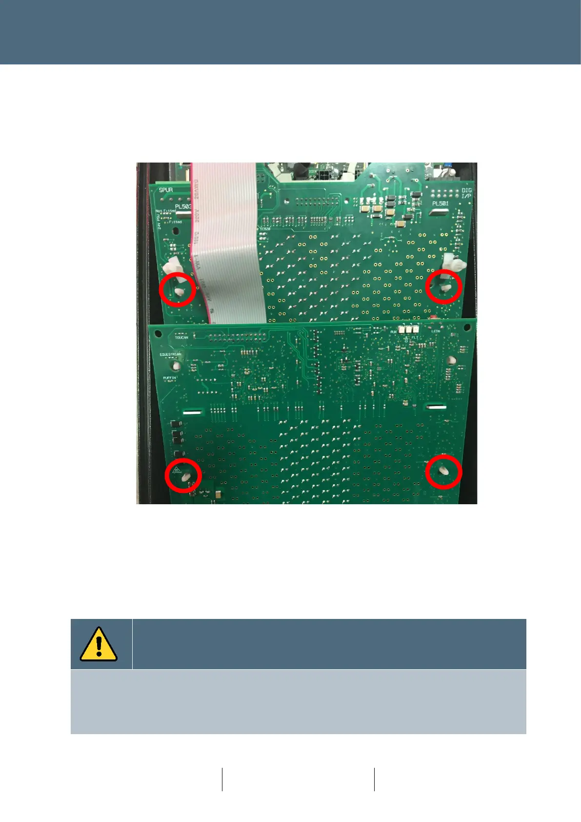
3. Release the Double stacked PCB by releasing the 4 fittings identified below. The top
fixings indicated have small release levers, the bottom fixings are friction only. Remove
the Red indicator PCB section first (bottom half of picture in Figure 79 below) and then
remove the Green section which lies partially underneath the Red section.
Figure 79 : Nearside Indicator with Fixings Identified.
Note the Nearside Green and Red sections are held together with a permanent ribbon cable
connection and cannot be separated. The two parts are fixed together using plastic
friction-lock fixings for secure shipment.
4. Remove the PCB and replace. Replacement is the reversal of removal.
For a single Node, the process to acknowledge an update does not require prior knowledge of the Serial
Number. However, it is good practice to note the New Serial Number and update any backups of the
Design Layout (paper or Electronic).
If multiple nodes are being replaced, then the Serial Number will need to be noted for configuration
update.