Page 48 of 176
667/HE/53000/000
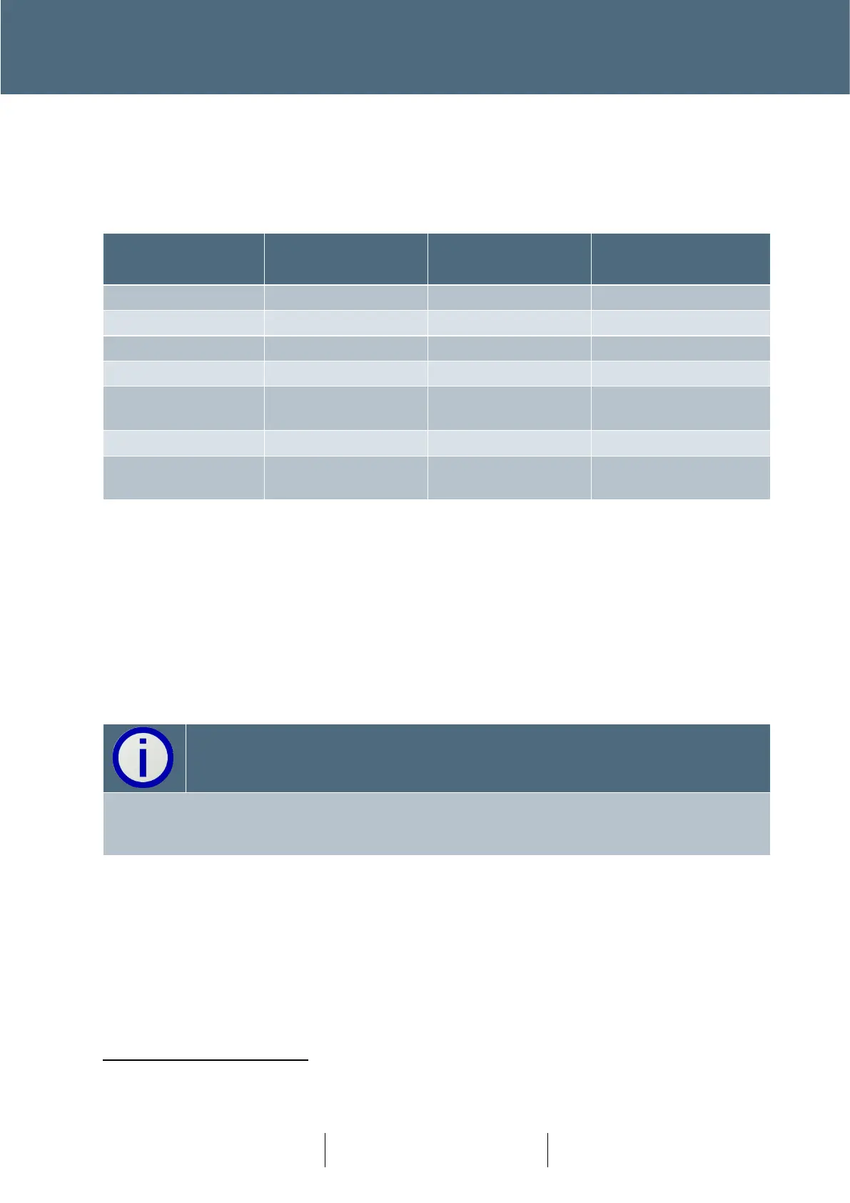
3.12.3 I/O Card Status LEDs
The I/O card has three tri-colour status LEDs as shown in
Figure 24, which are used to indicate various conditions
Green Toggle on
Receipt of Message
13
(As above depending
on state)
Table 7 – I/O Card LEDs
3.12.4 I/O Card Rotary Address Switch
This screwdriver-adjustable switch is located on the I/O card(s) as shown in
Figure 24 and is set up for the card address (before the controller is powered up) in accordance
with the appropriate Works Specification. The valid address range is 1 through 9. Address 0 is the
default address switch position for spare cards.
The address range is shared with the Intelligent Detector Backplane cards and must be unique.
The address range is limited to 1 to 9. Addresses 10 and above are used by the CTBs. Due to
architecture of Plus
+
this is not expected to be a practical limitation.
3.12.5 Parts
24in 16 out panel mounted module - 667/1/46085/001
24in 4 out panel mounted module - 667/1/46085/002
Conditions other than those identified above should not occur and can be treated as faults.
May flash so fast that it looks like Green Steady.