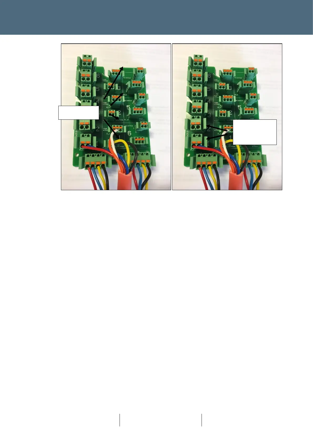
Figure 36 PTB with 4 Way street cable and Dropper Cable for the first Node
The power pair (Red and Blue) will be connected to the first supply column (PL15), which is also
numbered 1.
The data pair to the node (Yellow and Black) are connected to PL1 (labelled “To ByPass”). The data
pair from the node (Orange and White) are connected PL2 (labelled “From ByPass”).
In order to complete the circuit onwards to a downstream Node, a link pair (yellow and black) is
required from PL3 to PL12.
If a second node requires connection, then the next set of connectors are used (all labelled ‘2’)
and the link pair will then be moved to link PL5 to PL12.
Terminal blocks mounted on the opposite side of the PTB bracket are available for Spur
connections. Spur connections from PTB to Node use Red, Blue, Yellow and Black wires in the
Plus+ dropper cable (Orange and White wires are unused for Spur connections). Spur wiring from
the terminal block to the remote Node uses armoured street wiring.