11
Low Voltage Circuit Breaker
Electronic trip units (ETU)
1 Extended Instantaneous Protection (EIP) allows the WL breaker to be applied at the withstand rating 3 available
of the breaker with minus 0% tolerance; that means no instantaneous override whatsoever. EIP further – not available
enables the circuit breaker to be applied up to the full instantaneous rating of the breaker on systems
o optional
where the available fault current exceeds the withstand rating.
2 Ground Fault Module cannot be removed after installation.
Notes:
M = indicates phase loss sensitivity is enabled. LT pick-up reduced 80% when phase unbalance > 50%. ST = 20 ms
Communications -= Setting the parameters of the trip unit via the Breaker Data Adapter, MODBUS or PROFIBUS.
Key pad = Direct input at the trip unit.
G
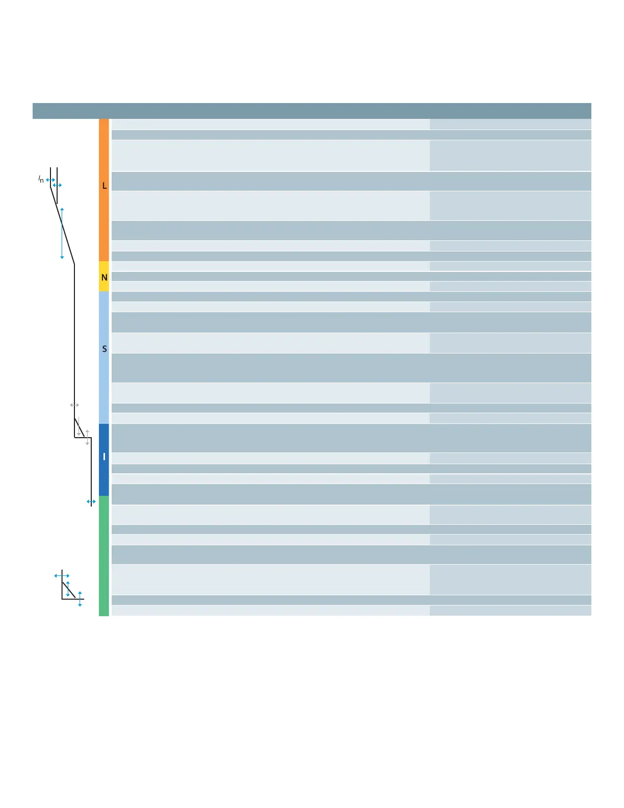
Basic functions ETU748 ETU776
Long-time overcurrent protection 3 3
Function can be switched ON/OFF – –
Setting range I
R
= I
n
x ... 0.4, 0.45, 0.5, 0.55, 0.... 1 (step: 1A)
0.6, 0.65, 0.7, 0.8,
0.9, 1
Switch-selectable overload protection
(I
2
t or I
4
t dependent function) 3 3
Setting range of time delay class t
R
at I
2
t
(seconds) 2, 3.5, 5.5, 8, 10, 2...30 (step; 0.1s)
14, 17, 21, 25, 30
Setting range of time delay t
R
at I
4
t
(seconds) 1, 2, 3, 4, 5 1...5 (step; 0.1s)
Thermal memory 3 (via slide switch) 3 (on/off via keypad or communications)
Phase loss sensitivity at t
sd
=20 ms (M) 3 (on/off via keypad or communications)
Neutral protection – 3
Function can be switched ON/OFF 3 (via slide switch) 3 (on/off via keypad or communications)
N-conductor setting range I
N
= I
n
x ... 0.5 ... 1 OFF 0.5 ... 2 OFF
Short-time delayed overcurrent protection 3 3
Function can be switched ON/OFF 3 (via rotary switch) 3 (on/off via keypad or communications)
Setting range I
sd
= I
n
x ... 1.25, 1.5, 2, 2.5, 1.25... 0.9 x I
cw
= max
3, 4, 6, 8, 10, 12 (step: 10A)
Setting range of time delay t
sd
, fixed
(seconds) M, 0.1, 0.2, 0.3, 0.4 M, 0.08... 04, OFF (step: 0.001s)
Switch-selectable short-time delay
short-circuit protection
(I
2
t dependent function) 3 (via rotary switch) 3 (via keypad or communications)
Setting range of time delay I
sd
at I
2
t
(seconds) 0.1, 0.2, 0.3, 0.4 0.1... 0.4 (step 0.001s)
Zone Selective Interlocking (ZSI) function per CubicleBUS module per CubicleBUS module
Instantaneous overcurrent protection 3 3
Function can be switched ON/OFF,
Extended Instantaneous Protection
is enabled when OFF – 3 (via keypad or communications)
Setting range I
i
= In x ... I
i
= I
cw
= EIP 1.5 x I
n
0.8 x I
cs
= OFF = I
cw
= EIP
Ground fault protection
2
O (field installable module) O (field installable module)
Trip and alarm function 3 3 (via keypad or communications)
Detection of the ground fault current
by residual summing method 3 3
Detection of the ground fault current
by direct sensing method 3 3
Setting range of the I
g
for trip A, B, C, D, E A... E (step: 1A)
Setting range of the I
g
for alarm A, B, C, D, E A... E (step: 1A)
Setting range of the time delay t
g
(seconds) 0.1, 0.2, 0.3, 0.4, 0.5 0.1...0.5 (step: 0.001s)
Switch-selectable
ground fault protection
(I
2
t / fixed) 3 3
Setting range time delay tg at I
2
t 0.1, 0.2, 0.3, 0.4, 0.5 0.1...0.5 (step: 0.001s)
ZSI ground function per CubicleBUS module per CubicleBUS module
WL Circuit Breaker selection and application guide

 Loading...


