10
WL Circuit Breaker selection and application guide
Low Voltage Circuit Breaker
ETU function overview
G
Basic functions ETU745
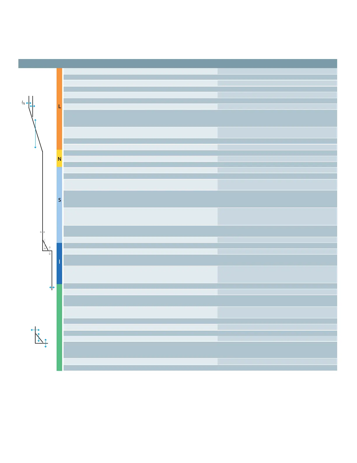
Long-time overcurrent protection 3
Function can be switched ON/OFF –
Setting range I
R
= I
n
x ... 0.4, 0.45, 0.5, 0.55, 0.6,
0.65, 0.7, 0.8, 0.9, 1
0.9, 1
Switch-selectable overload protection
(I
2
t or I
4
t dependent function) 3
Setting range of time delay class t
R
at I
2
t
(seconds) 2, 3.5, 5.5, 8, 10,
14, 17, 21, 25, 30
Setting range of time delay t
R
at I
4
t
(seconds) 1, 2, 3, 4, 5
Thermal memory 3 (via slide switch)
Phase loss sensitivity at t
sd
=20 ms (M)
Neutral protection 3
Function can be switched ON/OFF 3 (via slide switch)
N-conductor setting range I
N
= I
n
x ... 0.5 ... 1
Short-time delayed overcurrent protection 3
Function can be switched ON/OFF 3 (via rotary switch)
Setting range I
sd
= I
n
x ... 1.25, 1.5, 2, 2.5,
3, 4, 6, 8, 10, 12
Setting range of time delay t
sd
, fixed
(seconds) 0.02 (M), 0.1, 0.2,
0.3, 0.4, OFF
Switch-selectable short-time delay
short-circuit protection
(I
2
t dependent function) 3 (via rotary switch)
Setting range of time delay I
sd
at I
2
t
(seconds) 0.1, 0.2, 0.3, 0.4
Zone Selective Interlocking (ZSI) function per CubicleBUS module
Instantaneous overcurrent protection 3
Function can be switched ON/OFF,
Extended Instantaneous Protection
is enabled when OFF 3 (via rotary switch)
Setting range I
i
= I
n
x ... 1.5, 2.2, 3, 4, 6, 8, 10, 12
0.8 x I
cw
= Max,
OFF=Icw=EIP 1
Ground fault protection
2
O (field installable module)
Trip and alarm function 3
Detection of the ground fault current
by residual summing method 3
Detection of the ground fault current
by direct sensing method 3
Setting range of the I
g
for trip A, B, C, D, E
Setting range of the I
g
for alarm A, B, C, D, E
Setting range of the time delay t
g
(seconds) 0.1, 0.2, 0.3, 0.4, 0.5
Switch-selectable
ground fault protection
(I
2
t / fixed) 3
Setting range time delay t
g
at I
2
t 0.4, 0., 0.3, 0.4, 0.5
ZSI ground function per CubicleBUS module
1 Extended Instantaneous Protection (EIP) allows the WL breaker to be applied at the withstand rating 3 available
of the breaker with minus 0% tolerance; that means no instantaneous override whatsoever. EIP further – not available
enables the circuit breaker to be applied up to the full instantaneous rating of the breaker on systems
o optional
where the available fault current exceeds the withstand rating.
2 Ground Fault Module cannot be removed after installation.
 Loading...


