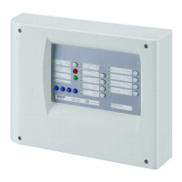
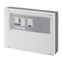
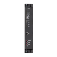
Accessories
54
Building Technologies A6V10257473_e_en_--
Fire Safety 2015-03-04
9.4.4 Connections and configuration
Repeaters can be powered directly from the XC10 24V output or from an external
power supply. Wiring depends on the type of power supply connection:
XC100x-A
(XCM1002)
ST6 ST7ST3 ST4 ST5
XC100x-A
(XCM1002)
External 24V
PSU
1
2
ST6 ST7ST3 ST4 ST5ST6 ST7ST3 ST4 ST5
ST6 ST7ST3 ST4 ST5 ST6 ST7ST3 ST4 ST5 ST6 ST7ST3 ST4 ST5
SW3 SW3 SW3
SW3 SW3 SW3
Contact 1 : mains fault
Contact 2 : battery fault
XT/XTA100x-A1
N° 1
SW5
OFF
XT/XTA100x-A1
N° 2
SW5
OFF
XT/XTA100x-A1
N° 16
SW5
ON
XT/XTA100x-A1
N° 1
SW5
OFF
XT/XTA100x-A1
N° 2
SW5
OFF
XT/XTA100x-A1
N° 16
SW5
ON
X18
X18
Fig. 38 XT/XTA1001-A1 – XT/XTA1002-A1 connection
Cable types :
è RTNet - Repeater powered from the XC10:
– 2 wires
– conductor cross section max.: 1.5mm
2
– twisted (at least 7 twists per meter) and shielded
è RTNet - Repeater powered from an external power supply:
– 3 wires between the power supply and the first repeater / 2 cores between
other repeaters
– conductor cross section max.: 1.5 mm
2
– twisted (at least 7 twists per meter) and shielded
è Power supply fault:
– 2 wires between the power supply and the first repeater
– conductor cross section max.: 1.5 mm
2
– twisted (at least 7 twists per meter)
è Power supply (all cases) :
– 2 wires
– conductor cross section max. : 1.5 mm
2
– Maximun RTNet line lengh : 1200 m
– Sub-stubs are not permitted

 Loading...


