Accessories
55
Building Technologies A6V10257473_e_en_--
Fire Safety 2015-03-04
Configuration
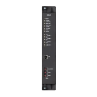
– SW5 : shall be switched to « ON » position on the last repeater of the RTNet
line, shall be switched to « OFF » position on all others repeaters
– SW3 : rotary switch for setting the repeater address (any address change shall
be followed by a reset of the repeater)
SW3 (pos.) 0 1 2 3 4 5 6 7 8 9 A B C D E F
repeater N° 1 2 3 4 5 6 7 8 9 10 11 12 13 14 15 16
9.4.5 Wiring recommandations
To guarantee a good EMC immunity, the following wiring recommandations must
be respected:
1. Cut the cable drain at the insulating sleeve
2. Twist the shield and connect it to the ST6-0V (repeater terminal side) and to
X5-4 (XC10 side) according to the drawing below
3. Twist the 2 cable wires and connect them to ST3 (repeater terminal side) and to
X12-9..10 (XC10 side) according to the drawing below
F3
F6 F5 F4
F2 F1
X14 X15 X16 X17
X11
1
X12
X10X27 1X9
1
X7X6
1
X5 11
ST4 ST3 ST5
ST6 ST7
SW3
Rtnet OUT
GNDGND
Supply
fault
24V OUTAddress 24V INRtnet IN
4
9

 Loading...


