29 von 37V 07.17
Service Manual BXT3-13/16/19
ENGLISH
Fitting
► Carry out assembly in the reverse order. Ensure for the correct positioning of the teeth between the cam disk
# 44 and tooth segment # 90 on exploded drawing.
► Tighten the cylinder screw # 151 and the cylinder screw #183 with a torque of 1.0 Nm.
► Screw the threaded pin # 86 until it ushes with the base plate.
5.8.2 Disassembly tensioning system BXT3-19
Dismantling
► Loosen the set screw # 85 and remove it from the base plate together with the pressure spring # 83 and pusher
# 84.
► Remove the side cover # 175 by loosening the three cylinder screws # 151 and cylinder screw # 183.
► Lift the rocker lever # 89 on exploded drawing, far enough so that the rocker # 50 can be pulled off to the outsi-
de.
► Remove the tensioning wheel # 46 together with outer ball bearing #18.
► Remove the shafts # 180. Then pull planet gears # 45 sideways out of the ange.
► The remaining ball bearing # 18 as well as the cam disk # 44 can now removed to the outside one by one in this
order.
Fitting
► Carry out assembly in the reverse order. Ensure for the correct positioning of the teeth between the cam disk
# 44 and tooth segment # 90 on exploded drawing.
► Tighten the cylinder screw # 151 and the cylinder screw # 183 with a torque of 1.0 Nm.
► Screw the threaded pin # 86 until it ushes with the base plate.
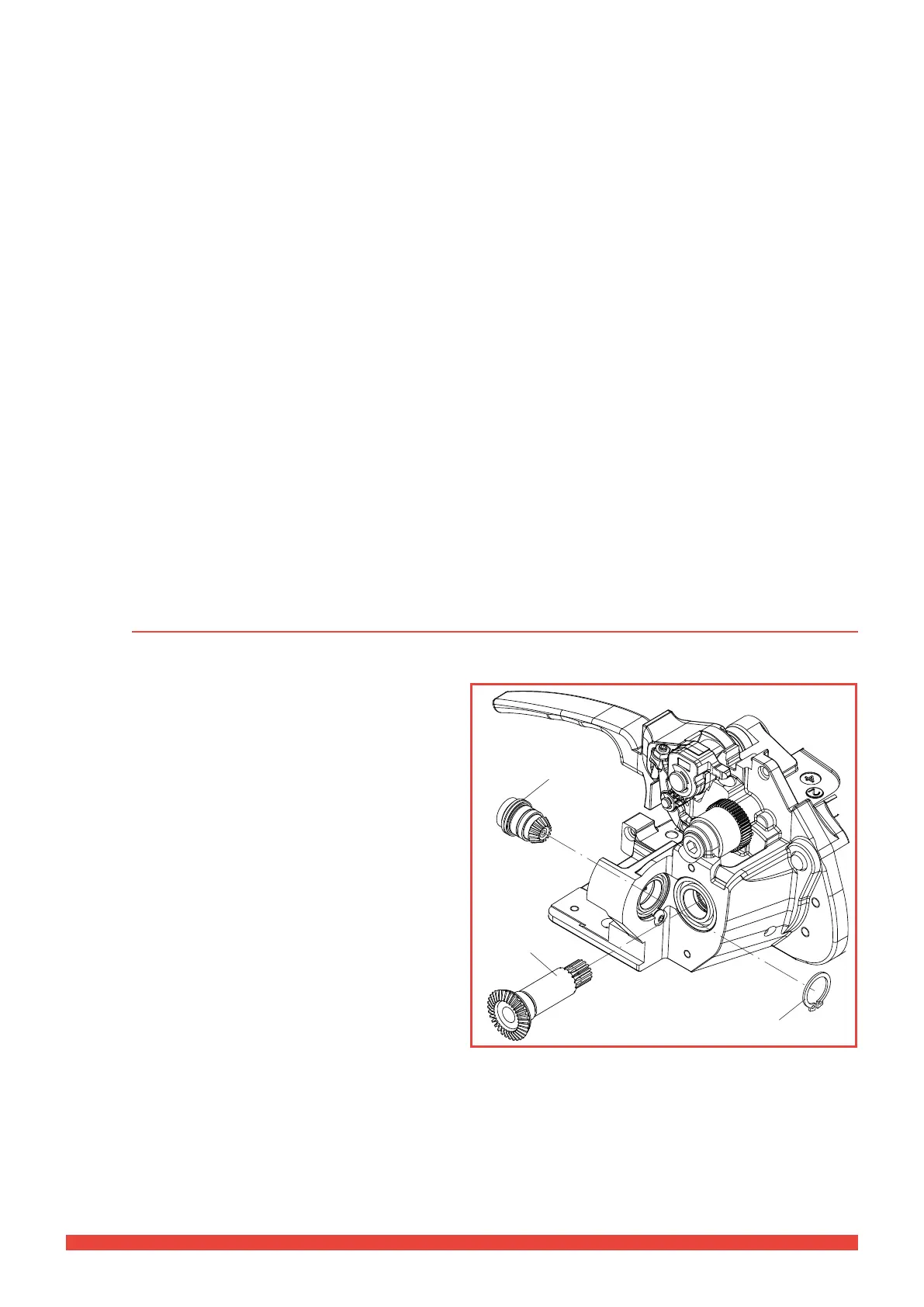
5.9 Gear
5.9.1 Disassembly of the bevel pinion
Dismantling
► Disassemble the welding mechanism from the base
plate (chapter 5.4.1).
► Remove the retaining ring # 136 from the bevel pinion
# 132 and remove the bevel pinion to the rear.
► Pull the bevel wheel with pinion # 12 from the base
plate.
Fitting
► Carry out assembly in the reverse order.
136
132
12