SIM5300E_Hardware_Design_V1.02
577uS 4.615mS
I
VBAT
VBAT
Max:300mV
Burst:2A
Figure 6: Reference circuit of the DC-DC power supply
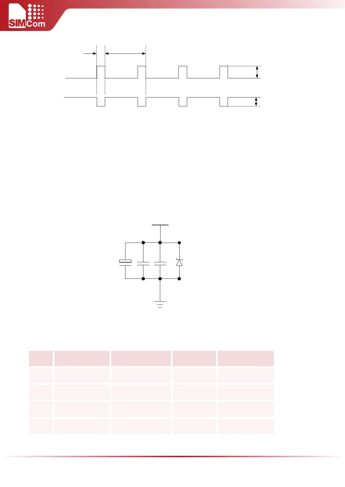
Using large tantalum capacitors (above 100uF) is the best way to reduce the voltage drops. For better RF
performance and system stability, some multi-layer ceramic chip (MLCC) capacitors (0.1/1uF) need to be used for
EMC, which have low ESR in high frequencies. Adding 33pF capacitors can effectively eliminate high frequency
interference. Note that capacitors should be put close to VBAT pins. Also, users should minimize the PCB trace
impedance from the power supply to VBAT pins by widening trace to 80 mils or more. It is suggested to use a
zener diode, and its reverse zener voltage is 5.1V and dissipation power is more than 500mW.The following figure
is the recommended circuit.
VBAT
5.1V
500mW
100uF
100nF
33pF
Figure 7: VBAT input application circuit
Table 6: Recommended zener diode models