SIM5300E_Hardware_Design_V1.02
4.6 SERIAL INTERFACES
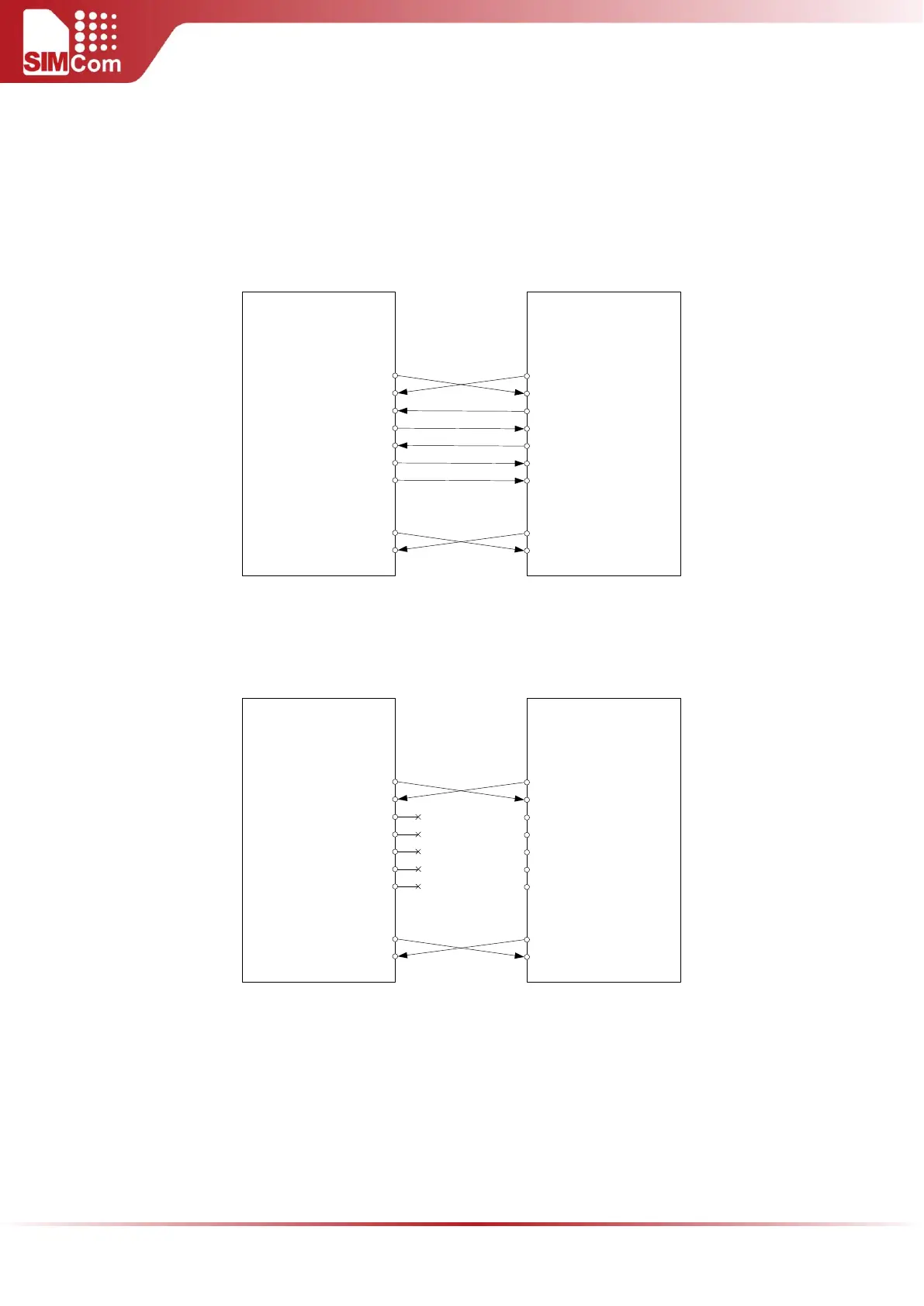
SIM5300E provides two unbalanced asynchronous serial ports. One is the serial port and the other is the
debug port. The module is designed as a DCE (Data Communication Equipment). The following figure shows
the connection between module and client (DTE).
TXD
RXD
RTS
CTS
DTR
DCD
RI
TXD
RXD
RTS
CTS
DTR
DCD
RING
MODULE (DCE)
CUSTOMER (DTE)
Serial port1
Serial port
Debug port
Serial port2
DBG_RX
DBG_TX
TXD
RXD
Figure 20: Connection of the serial interfaces
If only RXD and TXD are used in user’s application, other serial pins should be kept open. Please refer to
following figure.
TXD
RXD
RTS
CTS
DTR
DCD
RI
TXD
RXD
RTS
CTS
DTR
DCD
RING
MODULE (DCE)
CUSTOMER (DTE)
Serial port1
Serial port
Debug port
Serial port2
DBG_RX
DBG_TX
TXD
RXD
Figure 21: Connection of RXD and TXD only
The SIM5300E UART and Debug port are 1.8V voltage interface. If user’s UART/Debug application circuit is
3.3V voltage interface, the level shift circuits should be used for voltage matching. The following figure
shows the voltage matching reference design.