SIM5300E_Hardware_Design_V1.02
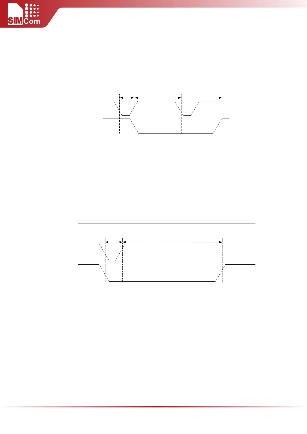
When the module works normally, if the user wants to restart the module, follow the procedure below:
Power down the module.
Wait for at least 15S after STATUS pin changing to low level.
Power on the module.
Power down
Delay > 15S
Restart
PWRKEY
STATUS
Figure 14: Timing of restart SIM5300E
4.3 EXTERNAL RESET
The external RESET pin is used to reset the module. This function is used as an emergency reset only when
AT command “AT+CPOWD=1” and the PWRKEY pin are of no avail. The reset timing is illustrated in the
following figure.
STATUS
(OUTPUT)
V
IL
< 0.6V
V
IH
> 1.3V
VBAT
NRESET
V
OH
> 1.6V
Typ: 100uS
Min: 8S
V
OL
< 0.2V
Figure 15: Reset timing
This pin is already pulled up in the module, so the external pull-up resistor is not necessary. A 100pF
capacitor close to the RESET pin is strongly recommended. A reference circuit is shown in the following
figure.