SIM5300E_Hardware_Design_V1.02
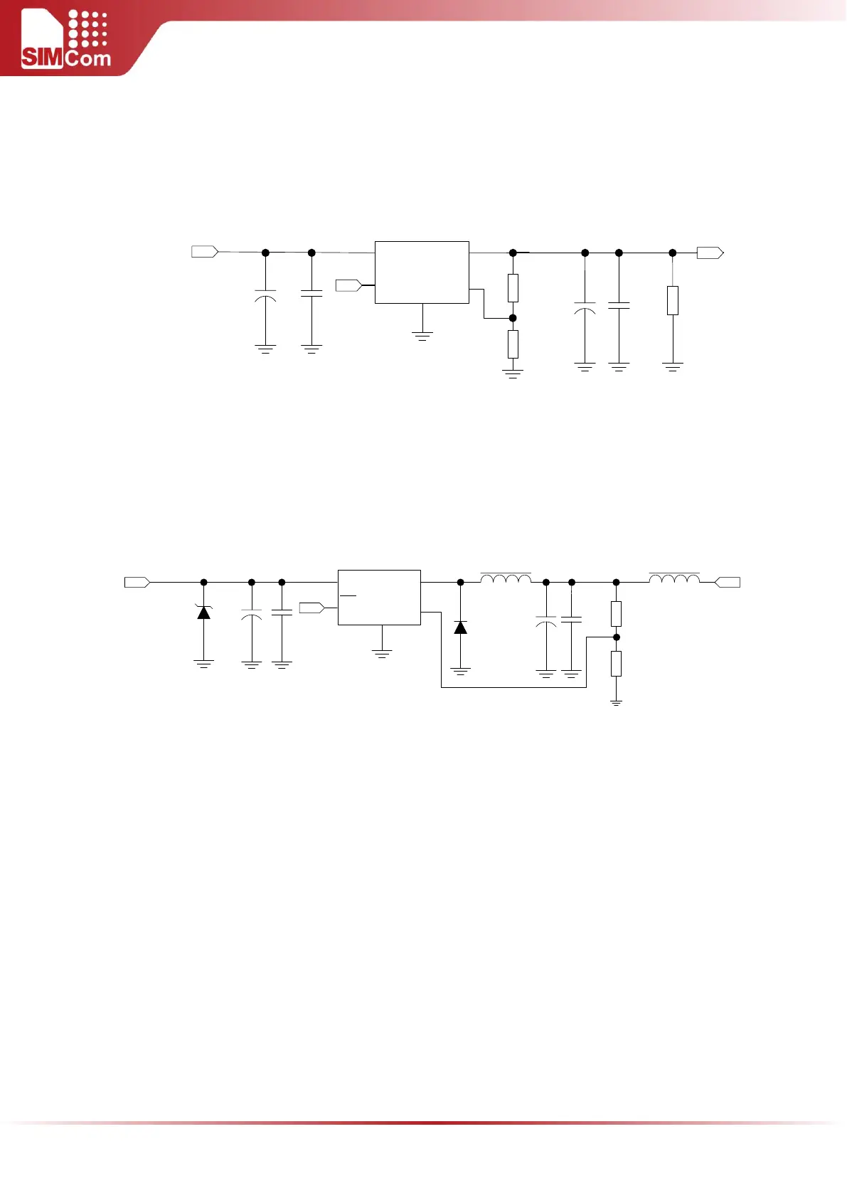
It is recommended that DC-DC or LDO should be used for the power supply of the module, make sure that
the peak current of power components can rise up to more than 2A.The following figure is the reference
design of +5V input power supply. The designed output of the power supply is 3.8V and a linear regulator
can be used here.
Vin
Vout
GND
FB
3
+
PWR_CTRL
R102
R101
VBAT
100K
47K
+
C103
100uF
C104
100nF
U101
MIC29302
5
4
1
2
C101 C102
100uF
1uF
DC INPUT
R103
470R
On/Off
Figure 8: Reference circuit of the LDO power supply
If there is a high drop-out between the input and the desired output (VBAT), a DC-DC power supply will be
preferable for higher efficiency. The following figure is the reference circuit. Note that DC-DC may influence
RF performance because of ripple current intrinsically.
SMBJ15A
TVS101
Vin Vout
ON/
OFF
GND
FB
U101
1
2
3
4
5
LM2596-ADJ
+
100uH
MBR360
L101
C101
+
C102
D102 C103
R102
R101
FB101
330uF
VBAT
2.2K
1K
100uF
1uF
PWR_CTRL
C104
100nF
270 OHM
DC input
Figure 9: Reference circuit of the DC-DC power supply
To monitor the power supply voltage, users can use the AT command “AT+CBC”. This command has two
parameters: the battery status and the voltage value (mV). It will return the capacity percentage and actual
value of battery (at the VBAT pin).
Note: The AT command “AT+CBC” can be used to monitor the VBAT voltage. For details, please refer
to document [1].
4.2 POWER ON/DOWN SCENARIOS
4.2.1 Power on SIM5300E
User can power on SIM5300E by pulling down the PWRKEY pin for at least 100ms and then release. This pin
is already pulled up to 1.8V internally, so external pull up is not necessary. Reference circuit is shown as
below.