SIM5300E_Hardware_Design_V1.02
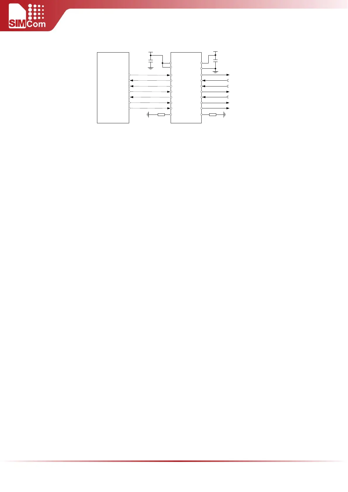
TXD
RXD
RTS
CTS
DTR
DCD
RI
A7
A1
A2
A3
A4
A5
A6
MODULE
UART port
A8
B7
B1
B2
B3
B4
B5
B6
B8
VCCA
OE
VDD_1V8 or
External 1V8
100nF
3.3V
100nF
VCCB
GND
TXD_3.3V
RXD_3.3V
RTS_3.3V
CTS_3.3V
DTR_3.3V
DCD_3.3V
RI_3.3V
47K 47K
Figure 22: Reference circuit of level shift
To comply with RS-232-C protocol, the RS-232-C level shift chip should be used to connect SIM5300E to the
RS-232-C interface, for example SP3238ECA, etc.
4.6.1 Function of Serial Port and Debug Port
Serial port:
Full modem device.
Contains data lines TXD and RXD, hardware flow control lines RTS and CTS, status lines DTR, DCD and RI.
Serial port can be used for CSD FAX, GPRS service and AT communication. It can also be used for multiplexing
function. For details about multiplexing function, please refer to document [3].
Serial port supports the following baud rates:
300, 1200, 2400, 4800, 9600, 19200, 38400, 57600, 115200, 230400 and 460800bps
Autobauding only supports the following baud rates:
From 1200 bps to 115200bps
The default setting is autobauding.
Autobauding allows SIM5300E to automatically detect the baud rate of the host device. Pay more attention
to the following requirements:
Synchronization between DTE and DCE:
When DCE powers on with autobauding enabled, it is recommended to send “AT” until DTE receives “OK”
response, which means DTE and DCE are correctly synchronized. For more information, please refer to the
AT command “AT+IPR”.
Note: User can use AT command “AT+IPR=x” to set a fixed baud rate and the setting will be saved to
non-volatile flash memory automatically. After the configuration is set as fixed baud rate, the URC
such as "RDY", "+CFUN: 1" and "+CPIN: READY” will be reported when SIM5300E is powered on.
4.6.2 Software Debug
Refer to the following figure for debugging software.