SIM5300E_Hardware_Design_V1.02
Top and Bottom View of SIM5300E:
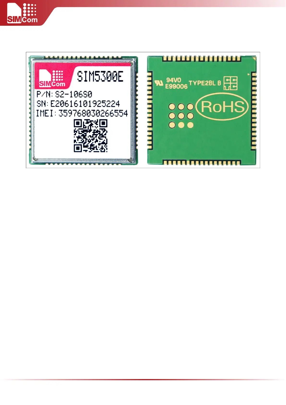
Figure 39: Top and bottom view of SIM5300E
Note: These test points are only used for module manufacturing and testing. They are not for
customer using.
For customer’s convenience, SIMCom provides a typical example of a commonly used soldering profile. In
final board assembly, the typical solder reflow profile will be determined by the largest component on the
board, as well as the type of solder/flux used and PCB stack-up. Therefore the soldering profile shown below
is only a generic recommendation and should be adjusted to the specific application and manufacturing
constraints.