Smart Machine Smart Decision
z Adjustable clock speed for LS/FS mode operation
z Support 7-bit/10-bit addressing
z Support high speed mode
z Support slave clock extension
z START/STOP/REPEATED condition
z Manual transfer mode
z Multi-write per transfer (up to 8 data bytes for non-DMA mode)
z Multi-read per transfer (up to 8 data bytes for non-DMA mode)
z Multi-transfer per transaction
z Combined format transfer with length change capability
Active drive/write-and I/O configuration
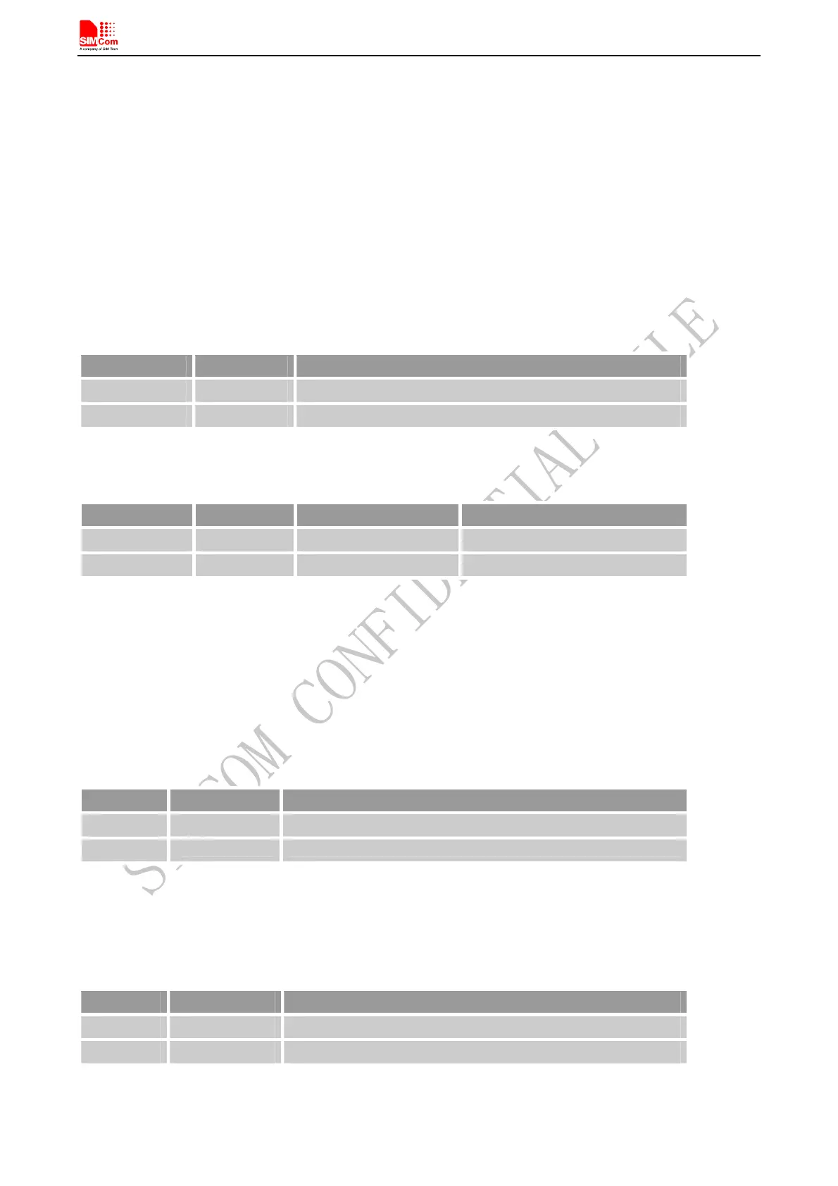
Table 25: Pin definition of the I2C
Pin name Pin number Description
SCL 39 I2C serial bus clock
SDA 38 I2C serial bus data
SIM808_Hardware Design_V1.00 2014.03.27
48
Note: I2C has been pulled up to 2.8V via 4.7KΩ.
Table 26: I2C multiplex function
Pin name Pin number Mode 0(default) Mode 1
SCL 39 SCL GPIO2
SDA 38 SDA GPIO1
4.13.1 General Purpose Input/Output (GPIO)
SIM808 provides 2 GPIO pins. The output voltage level of the GPIO can be set by the AT command “AT+
SGPIO”. The input voltage level of the GPIO can also be read by the AT command “AT+ SGPIO”. For more
details, please refer to document [1].
Table 27: Pin definition of the GPIO
Pin name Pin number
Reset state
GPIO6
44 Pull down
GPIO5
43 Pull down
4.14 ADC
Table 28: Pin definition of the ADC
Pin name
Pin number Description
ADC1 23 Analog to Digital Converter
ADC2 24 Analog to Digital Converter
SIM808 provides two auxiliary ADC, which can be used to measure the voltage. User can use AT command