Smart Machine Smart Decision
4.11.4 SD Card Interface
Module
DAT2
DAT3
CMD
VDD
CLK
VSS
DAT0
DAT1
MC3DA2
MC3DA3
MC3CM0
VDD_EXT
MC3CK
VSS
MC3DA0
MC3DA1
SD
card
Figure 42: SD reference circuit
If the VDD of SD card is 2.8V, user can use VDD_EXT power the SD card directly. If the VDD is 3.3V,
customer should design the power circuit external.
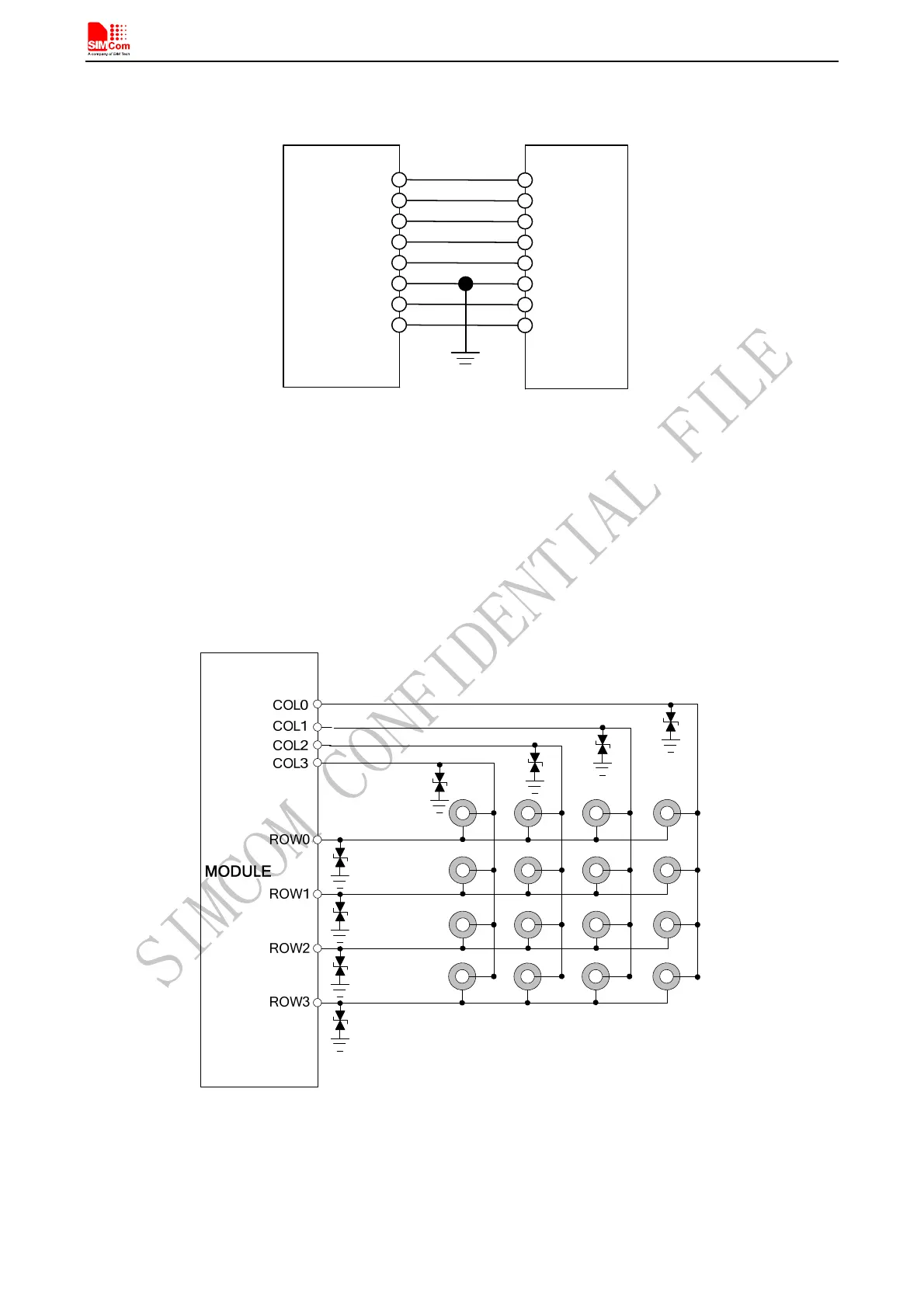
4.12 Keypad Interface
SIM808 consists of 4 keypad column outputs and 4 keypad row inputs, and it can support two kinds of
connections, the traditional 4*4 keypad matrix and the extended 4*4*2 keypad matrix.
Figure 43: Traditional keypad reference circuit
Note:1
、
According to the traditional 4*4 keypad matrix, when there are unused COLs or ROWs, user can execute AT command
to define unused COLs and ROWs as GPIO, for details please see the document [1].
2
、
Press COL0 and ROW0 or pull down COL0 when power-on(PWRKEY, Charging, RTC alarm), power sequence is USB
Download.
SIM808_Hardware Design_V1.00 2014.03.27
45