Smart Machine Smart Decision
VDD_EXT
4.7K
47K
RXD
4.7K
MCUTXD
Module
Customer
VDD_EXT
MCUVDD
Figure 26: RX level converting by transistor
Note: The recommend Transistors’ part numbers are 2SC4617TLR and PBHV8115Z. when update firmware via the TXD/RXD
circuit as figure 25 and figure 26 shows, customer should make sure the VDD_EXT has voltage output, or a external LDO should
be added to power VDD_EXT.
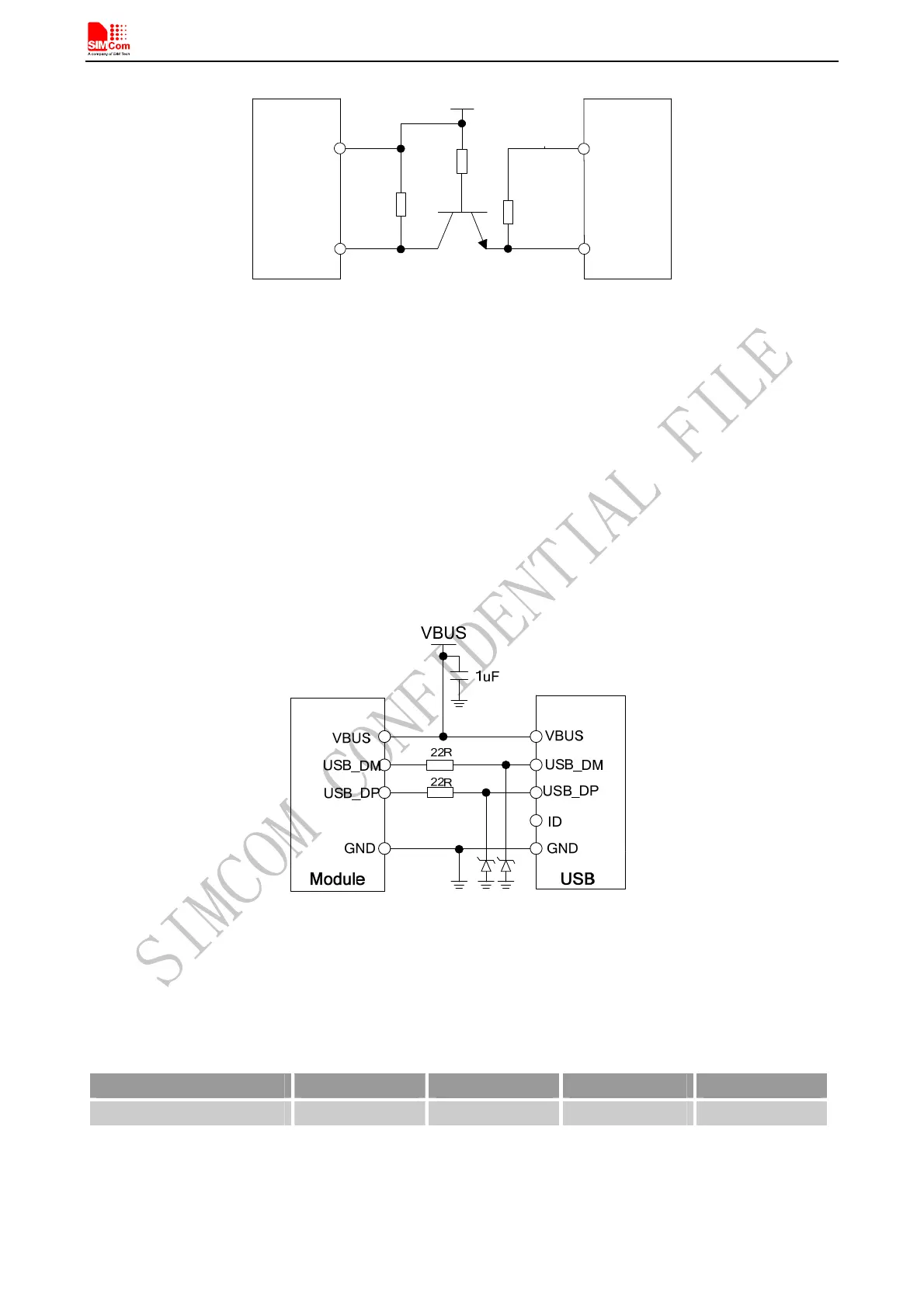
4.6.3 USB Interface
USB interface supports software debug function. When power on the module, connect VBUS, USB_DP,
USB_DM and GND to PC, then install the driver successfully, a UART port could be recognized by the PC,
customer could achieve the software Debug purpose with this UART port.
The following diagram is recommended:
Figure 27: USB reference circuit
The maximum allowable cap load of TVS on USB data line should be less than 5pF (e.g. ESD9L5.0ST5G and
ESD9M5.0ST5G). The USB_DP and USB_DM should be routed in differential traces.
Note: please reserve the USB interface or test point for debug.
Table 12: Serial port characteristics
Pin Min Typ Max Unit
VBUS 4.3 5 7 V
SIM808_Hardware Design_V1.00 2014.03.27
34