Smart Machine Smart Decision
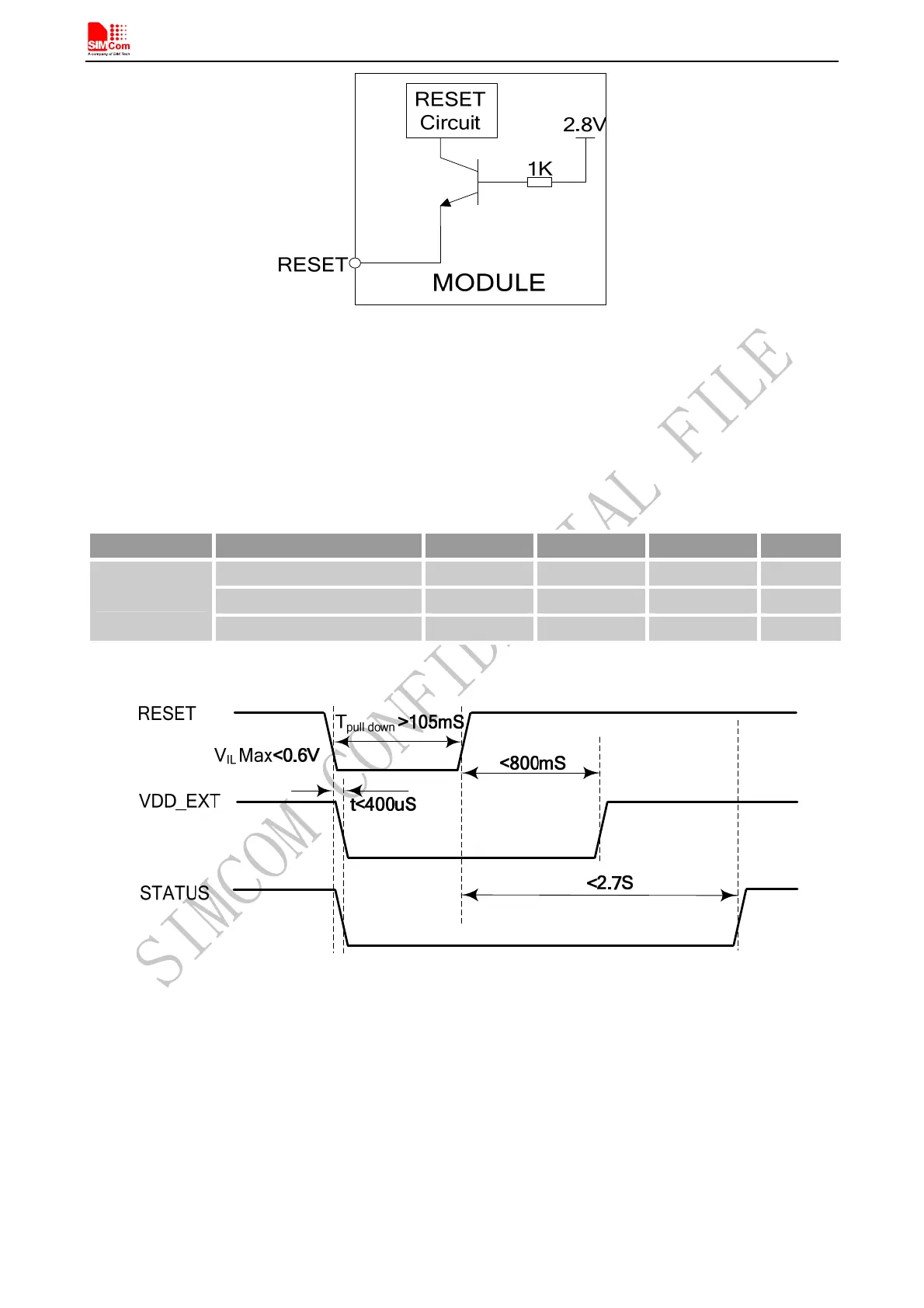
Figure 15: Reset Circuit
The typical value of RESET pin high level is 2.8V, so for the 3V or 3.3V, customer could use MCU’s GPIO to
driver this pin directly, resistor in serial the RESET signal could enhance the ESD performance but the value
should not be too high, otherwise the level of RESET could be lower than threshold value; RESET hardware
parameters can refer to the following table.
Table 7: Electronic characteristic of the RESET Pin
Pin name Symbol Min Typ Max Unit
V
IH
2.7 2.8 2.9 V
V
IL
- - 0.6 V
RESET
T
pull down
105 - mS
The reset scenarios are illustrated in the following figures.
Figure 16: Reset timing sequence
4.3 Power Saving Mode
User can control SIM808 module to enter or exit the sleep mode (AT+CSCLK=1) by DTR signal. When DTR is
in high level and without interrupt (on air and hardware such as GPIO interrupt or data in serial port), SIM808
will enter sleep mode automatically. In this mode, SIM808 can still receive paging or SMS from network but the
serial port is not accessible.
Note: Customer must shut off the power supply of GPS, and then the AT commands about the power saving mode can be
executed correctly, and the current consumption will be lower.
SIM808_Hardware Design_V1.00 2014.03.27
26