Smart Machine Smart Decision
4.18 RF Synchronization Signal
The synchronization signal serves to indicate growing power consumption during the transmit burst.
Table 36: Definition of the RF_SYNC pin
Pin name Pin number Description
RF_SYNC 63 Transmit synchronization signal
Note: Do not pull up RF_SYNC.
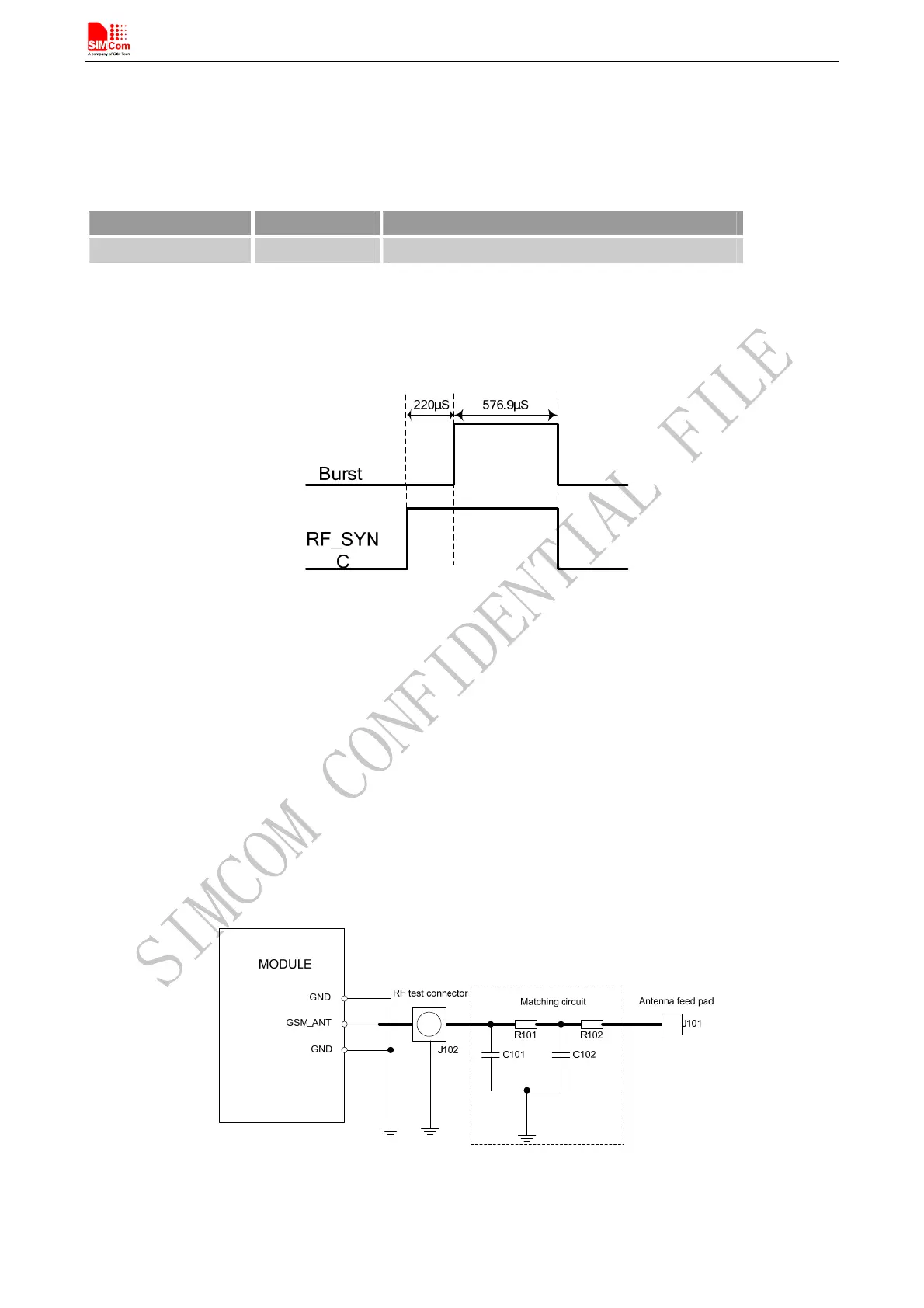
The timing of the synchronization signal is shown in the following figure. High level of the RF_SYNC signal
indicates increased power consumption during transmission.
Figure 49: RF_SYNC signal during transmit burst
4.19 GSM antenna Interface
GSM antenna port is named RF_ANT. The impedance should be 50. VSWR should be less than 2. It is
recommended that GSM antenna and Bluetooth antenna be placed as far as better to keep the isolations more than
30dB.
The customer’s GSM antenna also can be located in the customer’s main board and connect to module’s
GSM_ANT pad through microstrip line or other type RF trace which impendence must be controlled in 50. To
facilitate the antenna tuning and certification test, a RF connector and an antenna matching circuit should be
added. The following figure is the recommended circuit.
Figure 50: GSM antenna matching circuit
In this figure, the components R101,R102,C101 and C102 is used for antenna matching, the components’ value
SIM808_Hardware Design_V1.00 2014.03.27
51