Smart Machine Smart Decision
4.11 PCM Interface
SIM808 provides PCM interface.
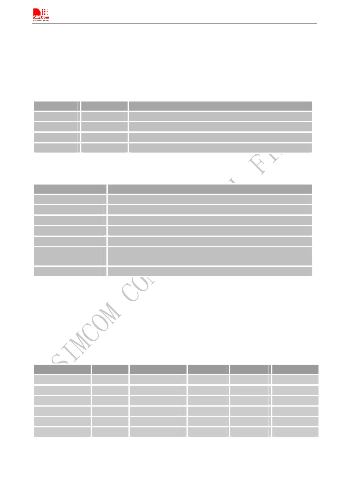
Table 20: PCM pin definition
Pin name Pin number Description
PCM_OUT 48 PCM data output
PCM_IN 47 PCM data input
PCM_SYNC 45 PCM synchrony
PCM_CLK 46 PCM clock
SIM808 PCM interface only supports master mode, data length is 16 bits (linear), and PCM clock rate is 256
KHz.
Table 21: PCM pin specification
Feature specification
Line Interface Format Linear(Fixed)
Data length 16bits(Fixed)
PCM Clock/Sync Source Master Mode(Fixed)
PCM Clock Rate 256Khz(Fixed)
PCM Sync Format Short sync/Long sync both support
Zero Padding/Sign extensi
on
Default Zero Padding
Data Ordering MSB/LSB both support
Note: User can use AT command control PCM interface, for details please refer to document [1].
4.11.1 PCM Multiplex Function
With GPIO5 and GPIO6, PCM interface can be configured as SPI or SD interface, the following table shows the
detailed multiplex function.
Table 22: PCM Multiplex Function
Name Pin number Mode 0(default) Mode 1 Mode 2 Mode 3
PCM_OUT 48 PCM_OUT GPIO10 MC3DA3 /
PCM_IN 47 PCM_IN DISP_DATA MC3DA2 GPIO9
PCM_SYNC 45 PCM_SYNC DISP_CS MC3CK GPIO7
PCM_CLK 46 PCM_CLK GPIO8 MC3CM0 GPIO8
GPIO6 44 GPIO6 DISP_CLK MC3DA1 /
GPIO5 43 GPIO5 DISP_D/C MC3DA0 /
Note: Multiplex Function need different software version.
SIM808_Hardware Design_V1.00 2014.03.27
43