Smart Machine Smart Decision
“AT+CADC” to read the voltage value. For details of this AT command, please refer to document [1].
Table 29: ADC specification
Parameter Min Typ Max Unit
Voltage range 0 - 2.8 V
ADC Resolution - 10 - bits
Sampling rate - - 1.0833 MHz
ADC precision 10 20 mV
Note: the voltage should less than 2.8V, or the ADC may be damaged.
4.15 PWM
Table 30: Pin definition of the PWM
Pin name Pin number Description
PWM1 42 PWM1, multiplex with GPIO4
PWM2 41 PWM2, multiplex with GPIO3
Note: SIM808 can only support 1 PWM synchronously, if customer set PIN 42 as PWM, so PIN41 can only be used as GPIO.
PWM output frequency varies from 0 to 2KHz.Two 7-bit unsigned binary parameters are used for the output
period and for the duty cycle. The AT command “AT + SPWM” is used to set the output period and duty cycle of
the PWM. For details, please refer to document [1].
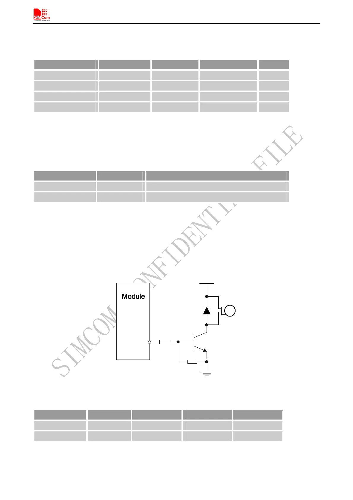
A typical circuit of the PWM drives buzzer is shown in the following figure:
4.7K
47K
VBAT
PWM
Figure 47: Reference circuit of PWM drive buzzer
Table 31: Buzzer output characteristics
Parameter Min Typ Max Unit
Working voltage 2.5 2.8 2.9 V
Working current 16 mA
Note: PWM pin must keep low when module in the boot process.
Table 32: PWM multiplex function
SIM808_Hardware Design_V1.00 2014.03.27
49