Page 47 of 60
5.4 Strobe Line Fault
Check EOL resistor (56k)
If ok, swap speaker lines to a different Zone (on amp)
Test to see if the fault has followed
IF YES – the fault could be in the field (wiring, devices)
IF NO – the fault is likely to be in the transformers/amplifiers
NOTE: A good way to test where a fault is located within the panel is swapping identical components
over and testing to see if the fault follows the device. This allows you to eliminate if the fault is
located on a device/card within the panel or out in the field wiring/devices.
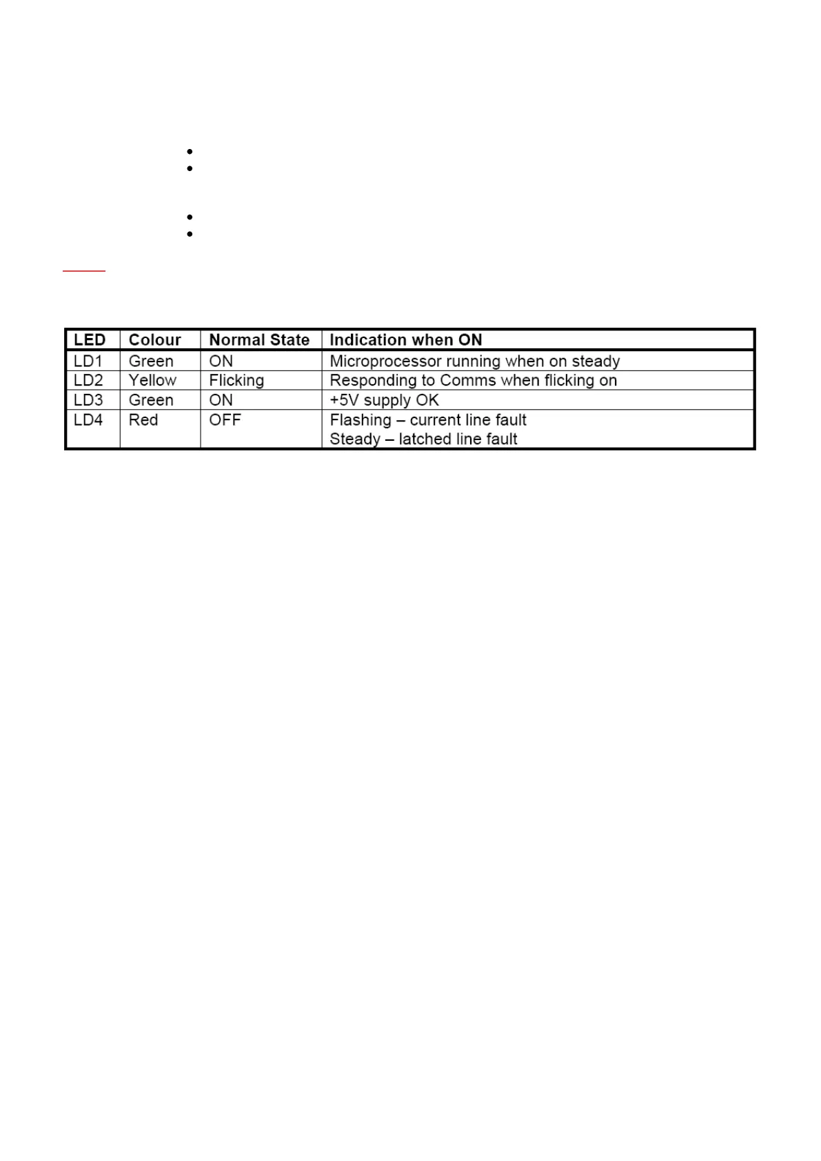
If a fault was present but all strobe outputs are now normal, the Red LED will be steady. This feature is designed
to assist in determining if an "Audio fault” indication on the ECP is/was an amplifier fault/speaker line fault or a
strobe line fault. To extinguish the steady red LED, switch the ECP to Isolate and back to Manual or Auto (all
software versions) or press and hold SILENCE for 2 seconds (ECP Version 2.0 and later).
5.4.1 Strobe Output Considerations
Having eliminated the strobe card as the Audio Line Fault there are some other considerations to keep in mind.
Strobe lights must be wired to the A and B terminals as shown in the diagram below (Strobe Relay Driver Module
and Strobe Light Connection).
The 2k7 resistor connected to each terminal pair when the system is shipped must be removed and connected to
the end of the strobe line. Keep in mind that the maximum load on each output is 2Amps. Loads higher then this
can blow fuses