9 - 7
9 Torque Generator Repair
Reassembly
26. Install the cross pin into the spool/sleeve.
27. Lubricate and install the washer into the valve hous-
ing.
NOTE: The input shaft seal has had two different config-
urations and both seal types (Quad or Lip), have been
addressed in the steps below.
28. In preparation of installing the quad seal, first install
the spool/sleeve assembly into the valve housing
backwards, shaft end up. Carefully retain the
spool/sleeve and washer assembly in the valve hous-
ing, and turn the assembly over, support it on a clean
flat surface. Temporarily installing these shaft parts in
the valve housing in the opposite direction from which
was originally intended will create a groove or pocket
into which the quad seal can be easily installed from
the input end of the valve housing.
29. Quad Seal Lubricate and install the quad seal in its
seat.
30. Quad Seal After seal installation, make sure the seal
is not twisted. Turn the valve housing over and
remove the spool/ sleeve assembly.
31. Lip seal Insert this seal into valve housing (without
shaft installed) from the inside and guide it with your
finger all the way into the seal groove, the seal lip
must be positioned so it is towards the inside of the
valve housing.
NOTE: Careful insertion of input shaft upon reassembly
will prevent shaft seal damage (step 32).
32. With the washer still resting firmly in the valve hous-
ing, lubricate the spool/sleeve assembly and carefully
install it in the valve housing shaft end down.
33. Lubricate the valve housing o-ring and install it into
the valve housing.
34. Install the control end spacer plate, aligning the cap
screw holes and porting passages with the matching
holes in the control valve housing.
35. Lubricate and install the o-ring in the groove located
in the spacer plate.
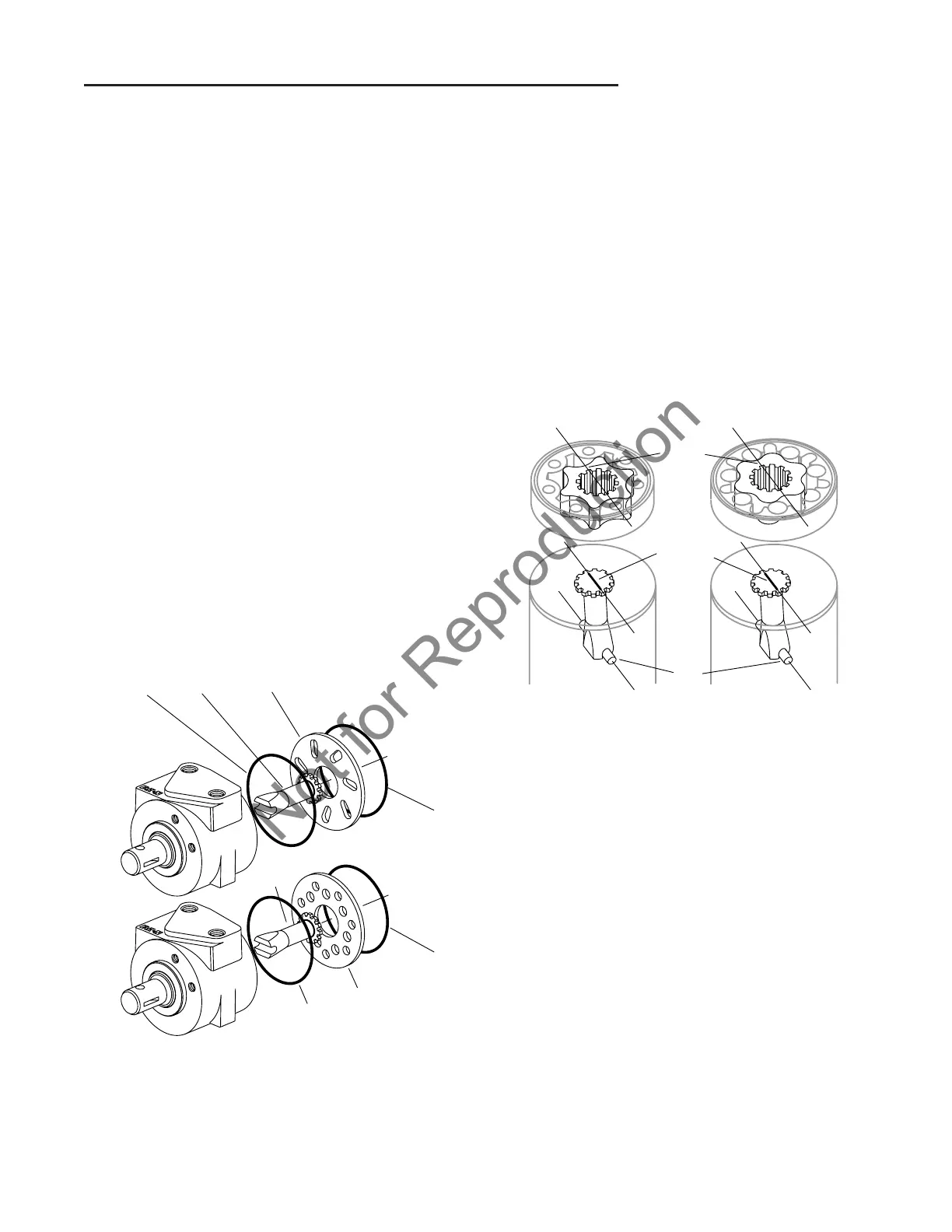
36. The preferred method of drive installation is to mark
the drive with a felt tip pen, as shown here. Mark the
splined end of the drive, from tooth-to-tooth, with a
line that parallels the slotted end of the drive. This
method helps assure proper alignment of the drive
and gerotor or Gerotor star (meter section).
37. Install the drive, make sure you fully engage the slot
on the end of the drive with the cross pin in the spool
and sleeve assembly.
38. This illustration (above) shows the correct relation-
ship of the spool/sleeve assembly cross pin and the
gerotor or Gerotor star for proper torque generator
timing.
39. With the o-ring groove side of the outer ring facing
upward, install the gerotor or Gerotor by aligning any
two star valleys with the previously marked drive.
After engaging the gerotor or Gerotor star with the
marked drive, rotate the outer ring of the gerotor or
Gerotor to align with the threaded holes in the valve
housing.