7 - 19
7 Electrical System Service
Location and Replacement
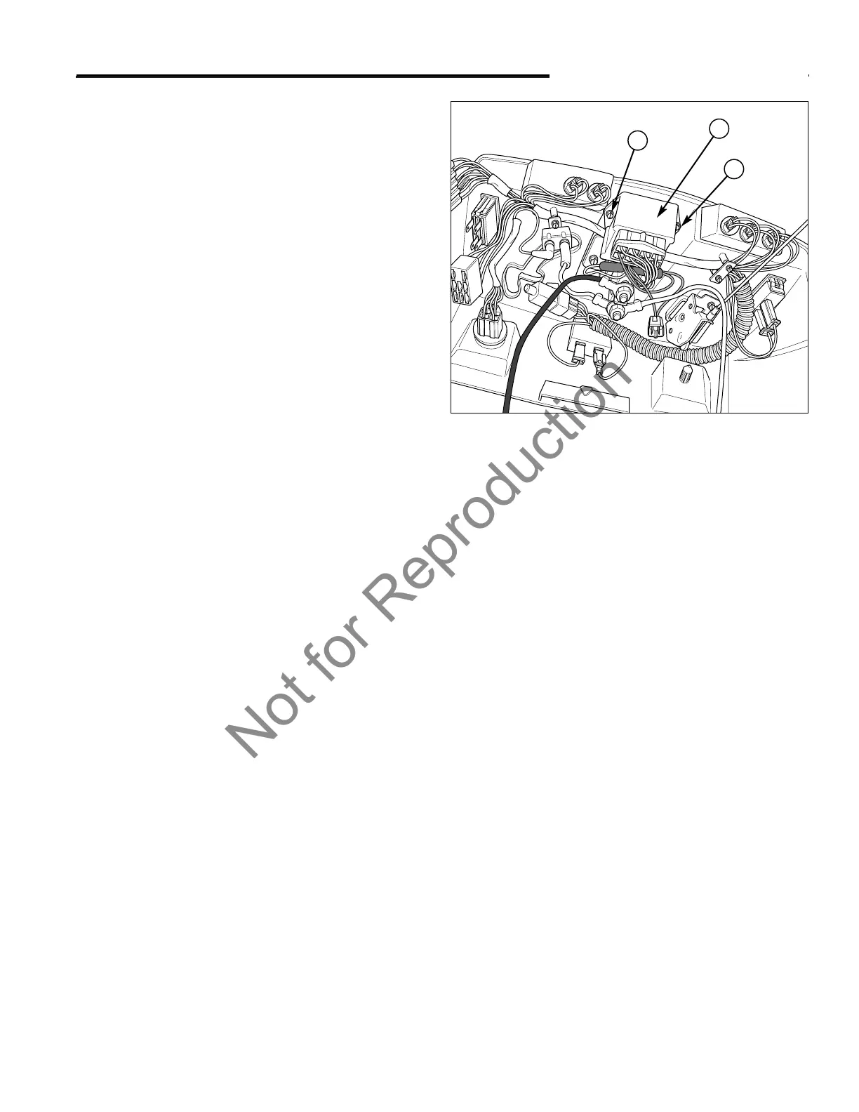
INTERLOCK MODULE
The safety interlock module (A, Figure 19) is located on
the underside of the dashboard.
1. Disconnect and secure the negative battery cable,
(see Section 6, COMMON SERVICE PROCE-
DURES).
2. Label and disconnect the wire harness.
3. Remove the plastite screws (B) securing the module
(A) to the underside of the dashboard.
4. Replace the module in the same orientation as the
original and install in reverse order.
VOLTAGE REGULATOR
The voltage regulator is installed on the engine as a
complete unit.
Refer to the engine manufacturer’s manual for specific
information regarding engine component testing and
replacement.
IGNITION COIL (MAGNETO)
Refer to the engine manufacturer’s manual for specific
information regarding engine component testing and
replacement.
OIL PRESSURE SENSOR
All models contain an oil pressure sensor (sender) which
is located on the engine.
Refer to the engine manufacturer’s manual for specific
information regarding engine component testing and
replacement.
ALTERNATOR
All models contain an alternator to charge the battery
and supply the tractor with electrical energy during oper-
ation.
Refer to the engine manufacturer’s manual for specific
information regarding engine component testing and
replacement.
To determine if the charging function of the alternator is
operating correctly, a basic check can be performed.
Refer to the Battery Charging Voltage Test in this sec-
tion.
Figure 19. Interlock Module
A. Interlock Module
B. Plastite Screws
A
B
B
FUEL SOLENOID
Refer to the tractor's specific engine manufacturer’s
instructions for service, repair, and replacement parts.
NOTE: Before beginning any work on the fuel pump or
fuel solenoid, disconnect and secure the negative battery
cable.