7 Electrical System Service
Location and Replacement
7 - 18
PTO CLUTCH
For replacement procedure, see PTO CLUTCH SER-
VICE section.
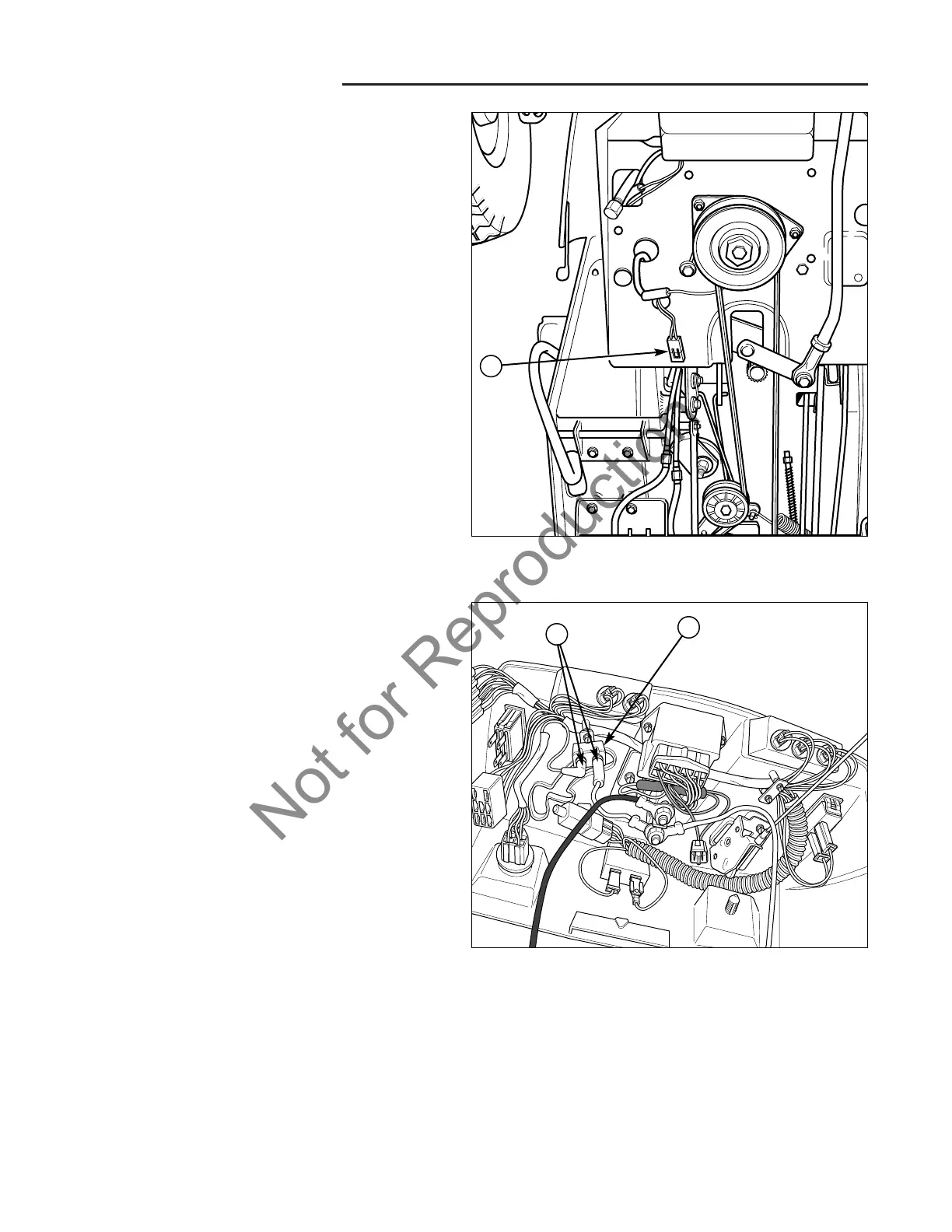
BRAKE PEDAL SWITCH
The brake pedal switch is located under right side of
frame, next to the pedal.
1. Disconnect and secure the negative battery cable,
(see Section 6, COMMON SERVICE PROCE-
DURES).
2. Elevate the front of the unit. (See Section 6, COM-
MON SERVICE PROCEDURES, Elevating Front End
for Safe Service.)
3. Label and disconnect the wire harness.
4. Squeeze the tabs on the side of the switch (A, Figure
17) and push the switch up into the fame.
5. Install switch in reverse order of removal.
Figure 17. Brake Pedal Switch
A. Brake Pedal Switch
A
Figure 18. Circuit Breaker Replacement
A. Circuit Breaker
B. Wires
CIRCUIT BREAKER
The circuit breaker (A, Figure 18) is located on the
underside of the dashboard.
1. Disconnect and secure the negative battery cable,
(see Section 6, COMMON SERVICE PROCE-
DURES).
2. Disconnect the wires (B) from the circuit breaker ter-
minals.
3. Remove the screw securing the body of the circuit
breaker to the dashboard and remove the circuit
breaker.
4. Install circuit breaker in reverse order of removal.
NOTE: The circuit breaker posts are marked “BAT” and
“AUX.” The BAT post should be connected to the battery
via the solenoid. The AUX post should be connected to
the ignition switch.
A
B