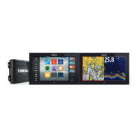
Power Control to ignition
Device will turn on once ignition is turned on to start engines. Connect the yellow wire to the
accessories output of the engine key switch.
Ú
Note: Engine start batteries and house batteries should have a common ground
connection.
1 Power cable connector to unit
2 Positive wire (red)
3 Ground wire (black)
4 Power control wire (yellow)
5 Alarm wire (blue)
6 Ignition switch
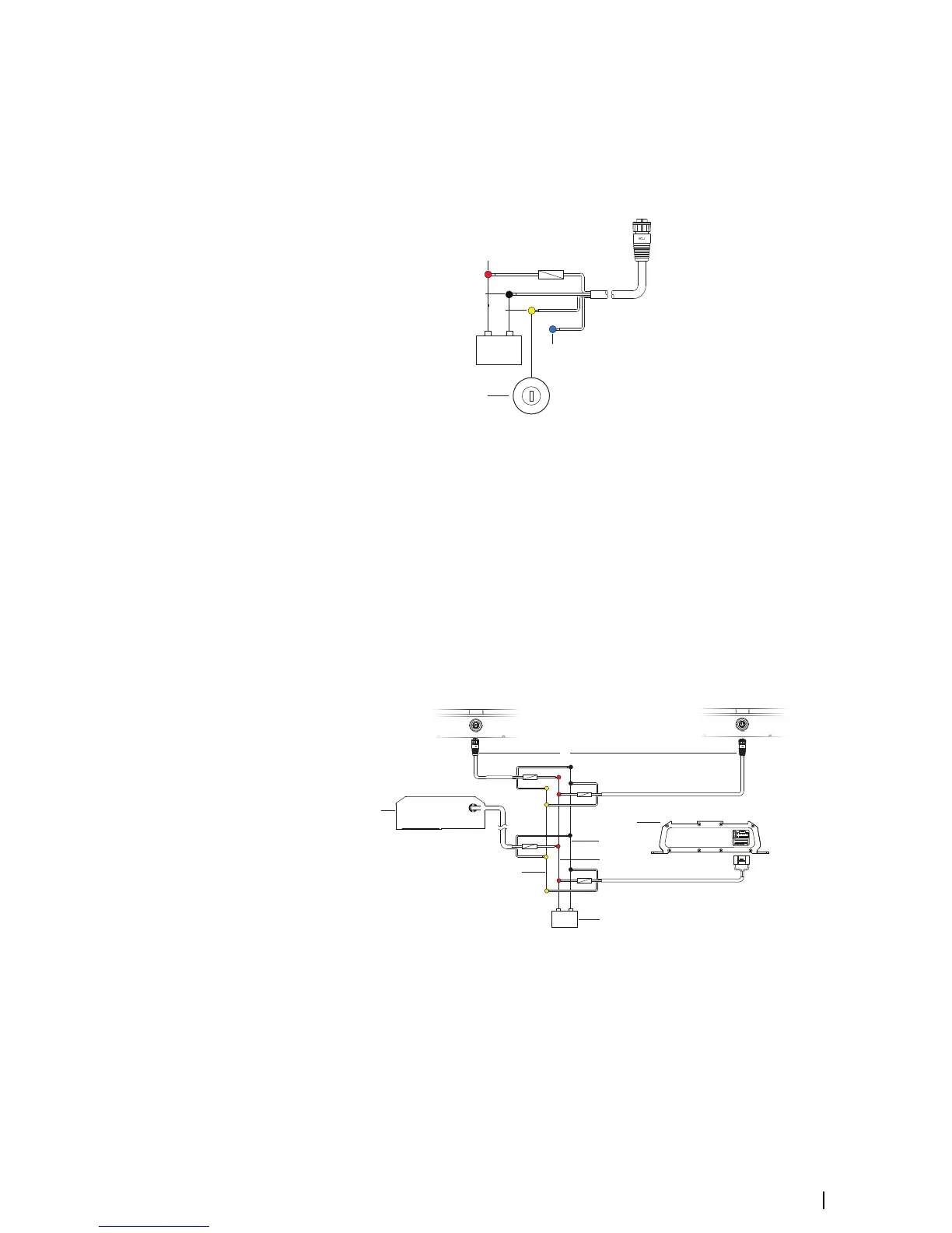
Power Control master/slave bus
Turning on the ‘master’ device turns on connected ‘slave’ devices.
A Power connection to unit on the left
B Power connection to unit on the right
1 Power cable connectors to units
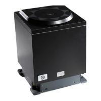
2 Radar interface box
3 Audio entertainment device (e.g. SonicHub2)
4 Ground wire (black)
5 Positive wire (red)
6 Power control wire (yellow)
Wiring | NSS evo3 Installation Manual
17

 Loading...