3rd party cables should be tested before installation. On runs over 10m it may be
required to add an HDMI amplifier or use HDMI-CAT6 adaptors.
Ú
Note: Some HDMI TV displays may apply over-scan, which will in effect crop the image
possibly causing loss of important content. Check the display manual for an option to
disable over-scan or adjust scaling
NMEA 2000 backbone
NMEA 2000 device connection
The NMEA 2000 data port allows the receiving and sharing of a multitude of data from
various sources.
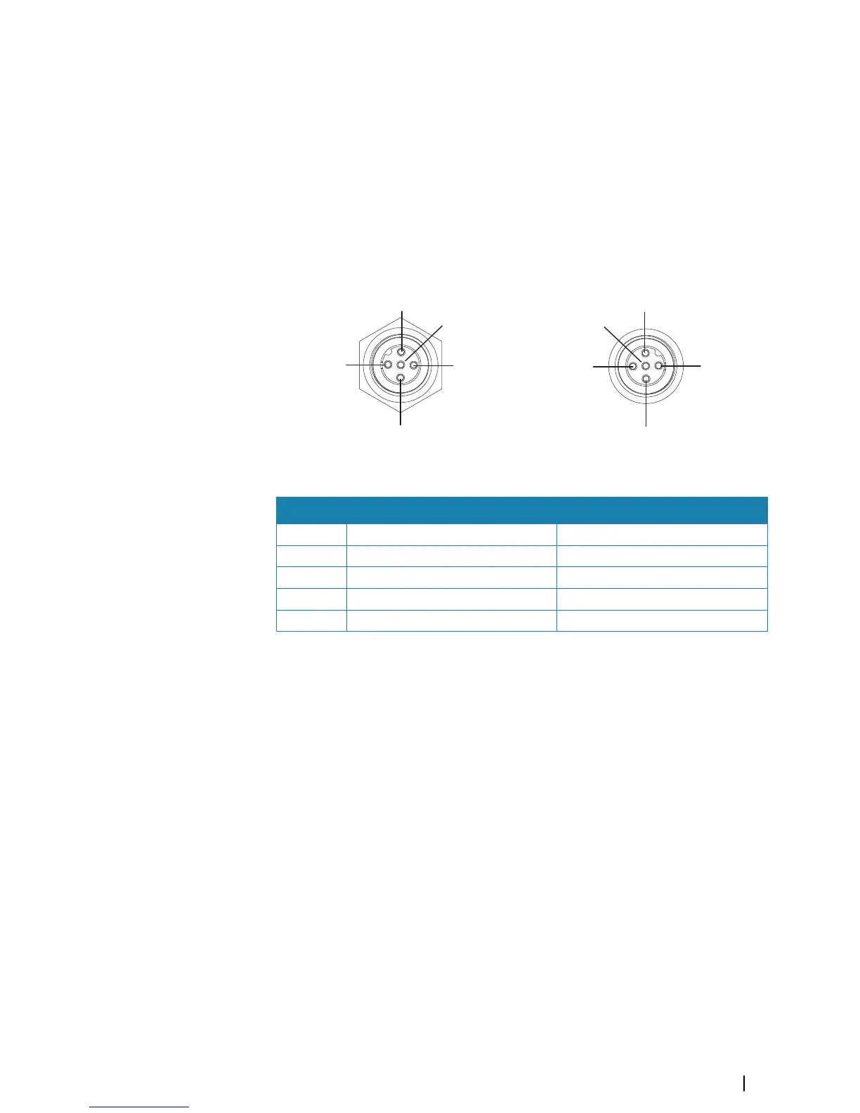
Cable plug (female)
Key Purpose Color
1 Shield Drain
2 NET-S (+12 V DC) Red
3 NET-C (DC negative) Black
4 NET-H White
5 NET-L Blue
Essential network information
The standardized physical cables/connectors for NMEA 2000 are Micro-C and Mini-C, directly
derived from the automation industries DeviceNET - Micro-C being the more commonly
used size.
• While most Navico products use Micro-C cabling and connectors, some products still use
proprietary SimNet connectors, which are easily made compatible with adaptor cables.
• A network consists of a linear backbone from which drop-cables connect to NMEA 2000
compliant devices.
• A single drop cable has a maximum length of 6 m (20 ft). The total length of all drop
cables combined should not exceed 78 m (256 ft).
• A NMEA 2000 network, using Micro-C cabling, has a maximum cable length of 100 m (328
ft), between any two points.
• A NMEA 2000 network needs to have a terminator at each end of the backbone. A
terminator can be one of the following:
- A terminator blank plug.
-
A wind transducer (where the mast cable is one end of the backbone).
Planning and installing a network backbone
The backbone needs to run between the locations of all products to be installed - typically in
a bow to stern layout - and be no further than 6 m from a device to be connected.
Choose from the following components to make up the backbone:
Wiring | NSS evo3 Installation Manual
19

 Loading...