4
1. Basic UI Elements
Reference
-
Font used in the printer GUI and the user manual is the “NANUM” font provided by NAVER.
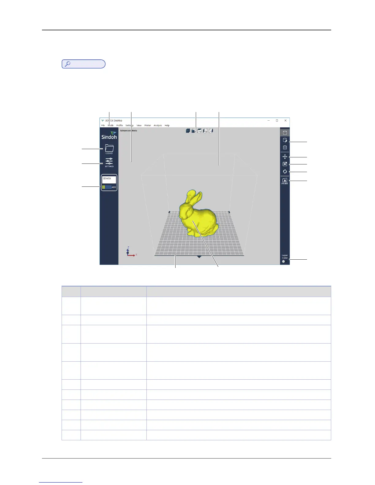
After installation is complete, double click on the icon created on your desktop, a screen similar to the following
appears. Explanation is as follows.
1 2 3
4
5
6
7
8
9
10
11 12
13
14
15
No. Name Explanation
1 Standard menu bar Most program functions are available in this menu bar. Opening files,Loading
preset values, Exporting program values and more functions available.
2 3D view Displays a reconstructed 3D model loaded on the program.
3 Select view angles You may look at the three-dimensional view from the front, back, left, right,
up, and down based on the selected angle.
4 Printer Domain In 3D view, displays actual printer domain showing the location and size of
the model.
5 View Mode Selection
button
On the screen 3 types of viewing modes are available. 3D Model Viewer,
Support Edit Viewer, Layer Viewer are available.
6 Position button Moves model in direction of 2 axes.
7 Scale button Changes the model’s size. (zoom or change length)
8 Rotation button Rotates object on set angles based on 3 axis.
9 Print button Connects to a printer to print a sliced model over the network.
10 Layer Color button Select colors to print by layers.
11 Printer frontal indication Indicates the front of the printout.