EasyManuals Logo
Home>SKF>Water Pump>MAX-1-2-24-X-R-V2

SKF MAX-1-2-24-X-R-V2 User Manual

SKF MAX-1-2-24-X-R-V2
47 pages
To Next Page IconTo Next Page
To Previous Page IconTo Previous Page
Page #18 background imageLoading...
Page #18 background image
18
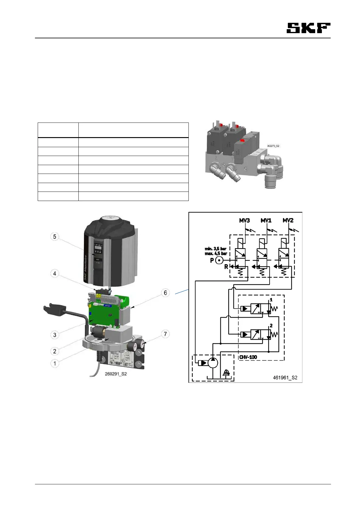
7.2 SKF Maxilube changeover valve unit
The changeover valve unit includes a solenoid valve group (4) and a control valve group (2), pressure gauges
(7) and a fixing plate which contains a bracket for the pump during the changing of the barrel. The Maxilube
pumping centre includes a user interface (5) and a circuit board (3).
Item Description
1
Control valve
2
CHV-100 control cartridge (1 or 2 pcs)
3
Circuit board ST105A
4
Solenoid valve 24 V
5
User interface IF-105
6
Power supply 115/230VAC
7
Pressure gauge
Figure 2: Construction & PI diagram of Maxilube
P
R
MV3
MV2 MV1

Table of Contents

Other manuals for SKF MAX-1-2-24-X-R-V2

Questions and Answers:

Question and Answer IconNeed help?

Do you have a question about the SKF MAX-1-2-24-X-R-V2 and is the answer not in the manual?

SKF MAX-1-2-24-X-R-V2 Specifications

General IconGeneral
BrandSKF
ModelMAX-1-2-24-X-R-V2
CategoryWater Pump
LanguageEnglish

Related product manuals