Page 43
EN
5. Design and function
5. Design and function
5.1 General information
The gear pump units are manufactured in
3 assemblies:
Series 1 is approved for very high viscosities
up to 1.000 mm
2
/s. They are characterized by
their simple and small design, and are accord-
ingly inexpensive. They are particularly suited
for small hydraulic and lubrication systems
that require volumetric flows between
0.06 l/min and 3 l/min for operating pressures
between 25 bar and 60 bar.
Series 2 and series 3 meet high requirements
in terms of volumetric flow, operating pressure
and efficiency. While series 2 has been de-
signed for volumetric flows of between 1 l/min
and 10.8 l/min, series 3 covers the range be-
tween 3.8 l/min and 36 l/min. Within the se-
ries, the permissible operating pressure is
greater the smaller the nominal volumetric
flow.
Due to the overlapping volumetric flow rang-
es, it is possible, for instance, to convey 9 l/min
using a series 2 pump in the low-pressure
range, whereas a corresponding series 3
pump can achieve this volumetric flow in the
5.2 Design and mode of operation of the
gear pump unit
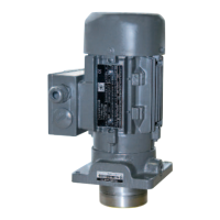
The gear pump units consist of motor, coupling,
flange and gear pump.
Electronic motors of performance class
0.18 kW are exclusively used for series 1. The
flange size is 116x116 mm for vertical pump
units (UC) and 80x120 mm for horizontal
pump units (UD).
In series 2, different motor classes are used
(0.18; 0.37; 0.55 and 0.75 kW). By combination
with gear pump units of different sizes
(1.2 cm
3
/revolution to 8 cm
3
/revolution), a
wide spectrum with regard to the selection
high-pressure range for the same efficiency.
The respective ranges of the series are shown
in a simple form in Fig. 1.
There are no restrictions with regard to the
mounting position of all the units. When UC
units are to be mounted lower than the maxi-
mum liquid level (oil reservoir), additional
sealing of the flange face is required, which
must be provided by the customer (refer to
version key).
criteria volumetric flow and operating pressure
is achieved. This means that this series begins
with a pump for 1 l/min at 200 bar and extends
to a pump for 10.8 l/min at 30 bar.
The flange size is 150x150 mm for vertical
pump units (UC) and 120x150 mm for hori-
zontal pump units (UD).
In series 3, electronic motors up to a nominal
output of between 0.75 and 4 kW are used.
The gear pumps have a pump constant of be-
tween 4.5 cm
3
/revolution and 26 cm
3
/revolution.
Series 3 begins with a pump of 3.8 l/min at
200 bar and extends to the biggest pump,
which delivers 36 l/min at 45 bar.
The flange size is 205x205 mm for vertical
pump units (UC) and 180x220 mm for hori-
zontal pump units (UD).