Page 17 of 66
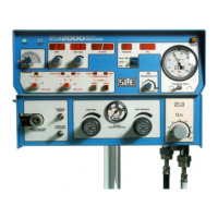
7.2 Function of Front Panel Controls and Indicators
Nº Item Description
1 POWER and
OPERATIONAL
MODE Switch
Selects Power OFF, ALARM TEST/CPAP, CMV,
PTV, SIMV modes.
2 POWER LED Indicates power is ‘ON’.
3 SYSTEM FAIL LED When this LED lights and the alarm sounds, it
indicates failure of the main processor. If this
happens, the ventilator must be removed from
service.
4 BPM digital display
with adjustment
knob
Displays between 1-250 BPM.
Available in two ranges: 1-125 BPM& 126-250
BPM, selectable by rear security key switch
5 INSP. TIME digital
display with
adjustment knob
Inspiratory Time
Displays 0.1-3.0 seconds in 1-125 BPM range
or 0.01-0.3 seconds in 126-250 BPM range.
6 FRESH GAS
BLOCK audible
alarm.
Indicates problems within the patient circuit line.
7 I:E RATIO digital
display
Displays from 9.9:1 to 1:9.9 calculated from BPM
and Insp. time
8 LEAK LED’s
audible alarm.
Indicates problems within the patient circuit line.
9 MAX MEAN MIN
switch with digital
PRESSURE display
Selects and displays Max., Mean or Min airway
pressures.
10 FIO
2
digital display Accurately displays the % O
2
as set by the Air-
Oxygen Blender.
11 TRIGGER BACK-
UP LED
Indicates a machine-delivered breath due to patient
failure to trigger ventilate or during back-up time
window.
12 MANUAL BREATH
Pushbutton
Causes delivery of a single breath in CPAP, CMV
and PTV modes to preset inspiration times and
pressures.
13 Pressure Gauge -6
to +60 cmH
2
O.
Proximal Airway Pressure. This pressure is
displayed more accurately by the independent
digital display.
14 PTV SENSITIVITY
control
Variable patient trigger level setting.
Sensitivity between 1(least sensitive to patient
effort) and 5 (most sensitive to patient effort).