6 Connection
SMA Solar Technology AG
Operating manual EDMM-10-BE-en-27 33
7. If the product is at the end of the RS485 bus, install
a jumper wire as a line terminator between pin 5
and pin 6 on the six-pole plug.
8. Plug the six-pole plug into the port X2 on the
product.
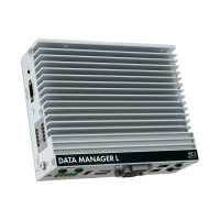
X3
X2
X4
X5
RS485
Digital
Input
ennexOS
D
A
T
A MANA
GER
6.5 Connecting the network
Interference in data transmission due to unshielded power cables
If unshielded power cables are used, they generate an electromagnetic field during operation
which may induce interference in network cables during data transmission.
• When laying network cables without separating strip, observe a minimum clearance of
200 mm (8in) to unshielded energy cables.
• When laying network cables with separating aluminum strip, observe a minimum
clearance of 100 mm (4in) to unshielded energy cables.
• When laying network cables with separating steel strip, observe a minimum clearance of
50 mm (2in) to unshielded energy cables.
Additionally required material (not included in the scope of delivery):
☐ 1 network cable
Network cable requirements:
The cable length and quality affect the quality of the signal. Observe the following cable
requirements:
☐ Cable type: 100BaseTx
☐ Cable category: minimum CAT5e
☐ Plug type: RJ45 of Cat5, Cat5e, Cat6 or Cat6a (Cat7 plugs cannot be used)
☐ Shielding: S/UTP, F/UTP or higher
☐ Number of insulated conductor pairs and insulated conductor cross-section: at least 2 x 2 x
0.22 mm² (2 x 2 x 24 AWG)
☐ Maximum cable length between 2 nodes when using patch cables: 50m (164ft)
☐ Maximum cable length between 2 nodes when using installation cables: 100m (328ft)
☐ UV-resistant for outdoor use.