6 Connection
SMA Solar Technology AG
Operating manual EDMM-10-BE-en-27 31
Circuitry overview:
6
K1
K2
K3
K4
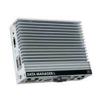
DATA MANAGER
1
2
3
4
5
Ripple control receiver
Fast-Stop
Figure 7: Connection of a Ripple Control Receiver
1. Connect the connection cable to the digital signal source (see the manual from manufacturer).
2. Connect the connection cable to the supplied six-pole plug. For this, unlock the required
terminal positions using a suitable tool and plug the conductors into these terminal positions.
3. Connect the six-pole plug to terminal X3. Observe the pin assignment.
4. Note the terminal assignment.
6.4 Connecting RS485 Devices
The product is suitable for the communication with RS485 devices via Modbus RTU.
The bytes in the product are set as follows and may need to be adjusted in the RS485 device.
Structure: 8 data bits
1 stop bit
No parity
Cable requirements:
The cable length and quality affect the quality of the signal. Observe the following cable
requirements.
☐ Number of insulated conductor pairs and insulated conductor cross-section: at least 2 x 2 x
0.22 mm² (2 x 2 x 24 AWG)
☐ Maximum cable length across the entire RS485 bus: 1200m (3937ft)
☐ Twisted pair conductors
☐ Cable with shielding: Yes
☐ UV-resistant for outdoor use.