6 Connection
SMA Solar Technology AG
Operating manual EDMM-10-BE-en-27 29
6 Connection
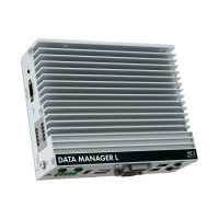
6.1 Overview of the Connection Area
X3
X2
X4
X5
RS485
Digital
Input
enne
xOS
D
A
T
A MANA
GER
X2
X5
X4
X3
− +
10-30V
DC
X1
RS485
enne
xOS
D
A
T
A MANA
GER
X1
Figure 5: Overview of the connection area
Connection Explanation
X1 Jack for connecting the voltage supply
X2 Jack for connecting the RS485 devices
X3 Jack for the connection of digital signals
X4 Network port with status LEDs for connecting to the SMA Speedwire network
X5 Network port with status LEDs for connecting to the SMA Speedwire network
6.2 Preparing the Connection Cable
Always proceed as follows to prepare each connection cable for connection to multipole plugs.
Procedure:
1. Strip 40mm (1.57in) of cable sheath from the end of the connection cable to which the
multipole plug is to be attached. When doing so, ensure that no pieces of cable fall into the
enclosure.
2. Strip off 6mm (0.24in) of the conductor insulation from each of the required connection
cable conductors.
3. Trim unneeded insulated conductors of the connection cable flush with the cable sheath.
4. If needed, push 1 bootlace ferrule onto 1 stripped insulated conductor as far as it will go and
crimp using a crimping tool.
6.3 Connecting Signal Source to Digital Input
Digital signals for the active power supply can be transmitted to the jack X3. A ripple control
receiver or a remote terminal unit can be used as a digital signal source, for example.
☐ Digital signal source with up to 4 potential-free contacts