TP301 – Operation, Maintenance and Instructions Manual
1.8
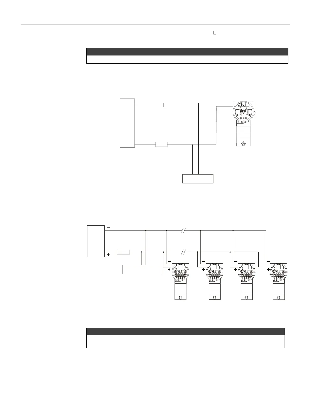
The TP301 is protected against reverse polarity, and supports 50 mA without damage.
The following figures show the possibilities for TP301 connections.
For proper operation, the configurator requires a minimum load of 250 Ohm between it and the power supply.
The configurator can be connected to the transmitter communication terminals or at any point of the
signal line by using the interface IF3 with alligator clips.
It is also recommended to ground the shield of shielded cables at one end only. The non grounded
end must be carefully isolated.
SIGNAL LOOP MAY BE GROUNDED AT
ANY POINT OR LEFT UNGROUNDED.
250
POWER SUPPLY
- -
+
+
CONFIGURATOR
Figure 1.9 - TP301 Wiring Diagram
The Figure 1.10 shows a typical TP301 connection in multidrop configuration. Such configurations
allow a maximum of 15 transmitters on the same line connected in parallel. Take care to the power
supply capacity as well, when many transmitters are connected on the same line.
15*14131
POWER
SUPPLY
* MAXIMUM NUMBER WITHOUT CONSIDERING INTRINSIC SAFETY
250
CONFIGURATOR
Figure 1.10 - TP301 Wiring Diagram for Multidrop Configuration
Make sure that the transmitter is operating within the operating area as shown on the load curve.
Communication requires a minimum load of 250 Ohm.