Section 4
4.1
MAINTENANCE PROCEDURES
General
Smar TP301 Position Transmitters are extensively tested and inspected before delivered to the end
user. Nevertheless, during their design and development, Smar considered the possibility of repairs by
the end user, if necessary.
In general, it is recommended that the end user do not try to repair printed circuit boards. Instead, he
should have spare circuit boards, ordered from Smar whenever necessary.
Recommendations for mounting Approved Equipment with the IP66/68 W
certifications (“W" indicates certification for use in saline atmospheres)
The certification is valid for stainless steel transmitter manufactured, approved with the certification
IP66/68 W. All transmitter external material, such as plugs, connections etc., should be made in
stainless steel.
The electrical connection with 1/2” – 14NPT thread must use a sealant. A non-hardening silicone
sealant is recommended.
The instrument modification or replacement parts supplied by other than authorized representative of
Smar is prohibited and will void the certification.
Diagnostic with Configurator
In case any malfunction related to the transmitter output, investigation may be carried out with the
configurator, as long as the transmitter is powered, the communication and the processing unit are
operating normally.
Connect the configurator to the transmitter according to the wiring diagram shown on Section 1.
ERROR MESSAGES
When communicating using the configurator the user will be informed about any problem found by the
transmitter self diagnostics.
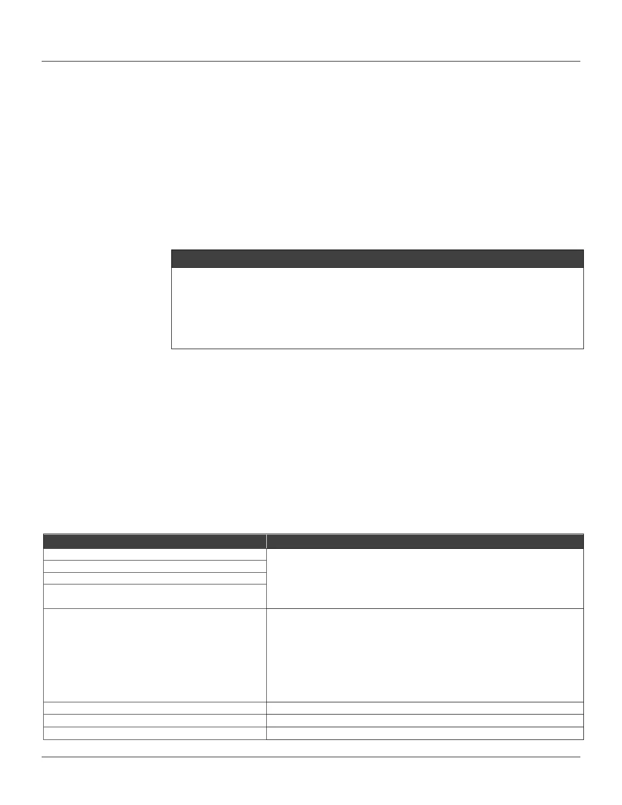
The messages always alternate with the information on the top line. The table below lists the error
messages, potential source of malfunction and more details on corrective action.
POTENTIAL SOURCE OF PROBLEM
• The line resistance is not according to technical characteristics.
• Excessive noise or ripple.
• Low level signal.
• Interface damaged.
• Power supply or battery voltage of the configurator lower than 9 V.
• Transmitter line resistance is not according to technical characteristics.
• Transmitter not powered.
• Transmitter not connected or damaged.
• Transmitter configured in multidrop mode being accessed by “ON LINE SINGLE
UNIT”.
• Transmitter reversely powered (Polarity is reversed).
• Interface damaged.
• Power supply or battery voltage of the configurator lower than 9 V.
• Other device using the line.
• Software version not compatible between configurator and position transmitter.
• Transmitter carrying out an important task, e.g., local adjustment.