Section 3
3.1
CONFIGURATION
The TP301 is configured via Local Adjust or configurators with digital communication (HART
®
Protocol). It is also possible to configure the TP301 via the CONF401 configuration tool or any
FDT/DTM software application, both for desk or laptop.
To enable local adjustment, the jumper “W1" located on top of the main board shall be connected to
the pins where the word “ON” is engraved on the circuit board. See Figure 3.2.
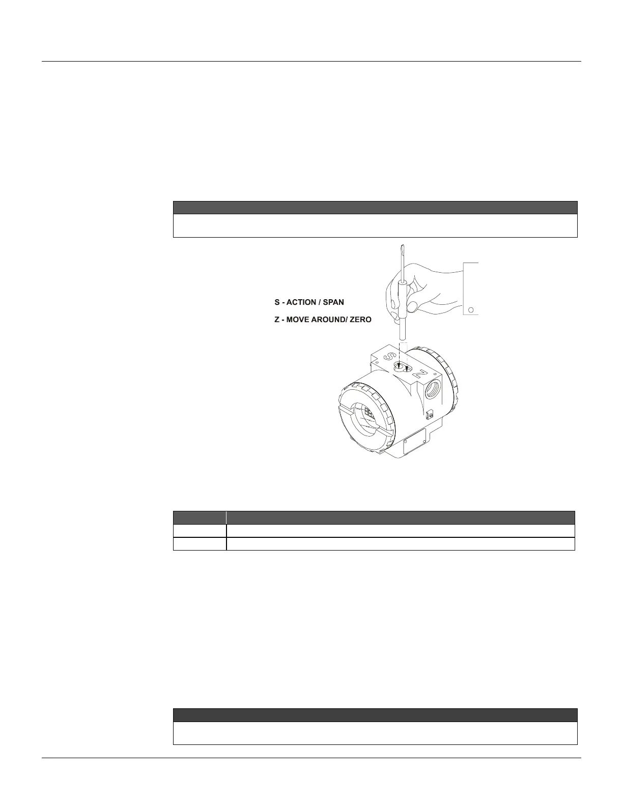
There are two orifices on the position transmitter, under its nameplate, identified by S and Z
respectively, which provide access to two magnetic switches actuated by means of a magnetic tool.
In this section the “magnetic tool” will be referred to as “TOOL”, and the orifices identified by “S” and “Z” will be
“S” orifice and “Z” orifice, respectively.
Figure 3.1 - Orifices of Local Adjustment
The table below shows the results of actions on “Z” and “S” on the TP301.
Browsing the programming tree function.
Selects the displayed function.
The digital display is necessary for local adjustment programming.
Jumper Connection
Simple Local adjustment - W2 Jumper connected in SI
If the W2 jumper is connected in SI (see Figure 3.2), simple local adjustment enabled; the
calibration can be done at the position of 0% inserting the cable of the tool in the Z orifice and 100%
inserting it in the S orifice.
Complete Local adjustment - W2 Jumper Connected in COM
With the jumper connected in COM (see Figure 3.2), complete local adjustment enabled, allowing to
change the displayed unit direct or reverse indication and to calibrate the lower position (LOPOS) or
the upper position (UPPOS).
After configuring these parameters, we recommend to leave the W1 jumper in OFF (disabled) to
avoid accidental mis-configuration.