Maintenance Procedures
4.3
Transducer
To remove the transducer from the electronic housing, disconnect before the electrical connections (in
the field terminal side) and the main board.
Loosen the hex screw (6) and carefully unscrew the electronic housing from the transducer, observing
that the flat cable is not excessively twisted.
Electronic Circuit
To remove the circuit board (5) and indicator (4), first loose the cover locking (7) on the side not marked
“Field Terminals”, then unscrew the cover (1).
The boards have CMOS components which may be damaged by electrostatic discharges. Observe correct
procedures for handling CMOS components. It is also recommended to store the circuit boards in electrostatic-
proof cases.
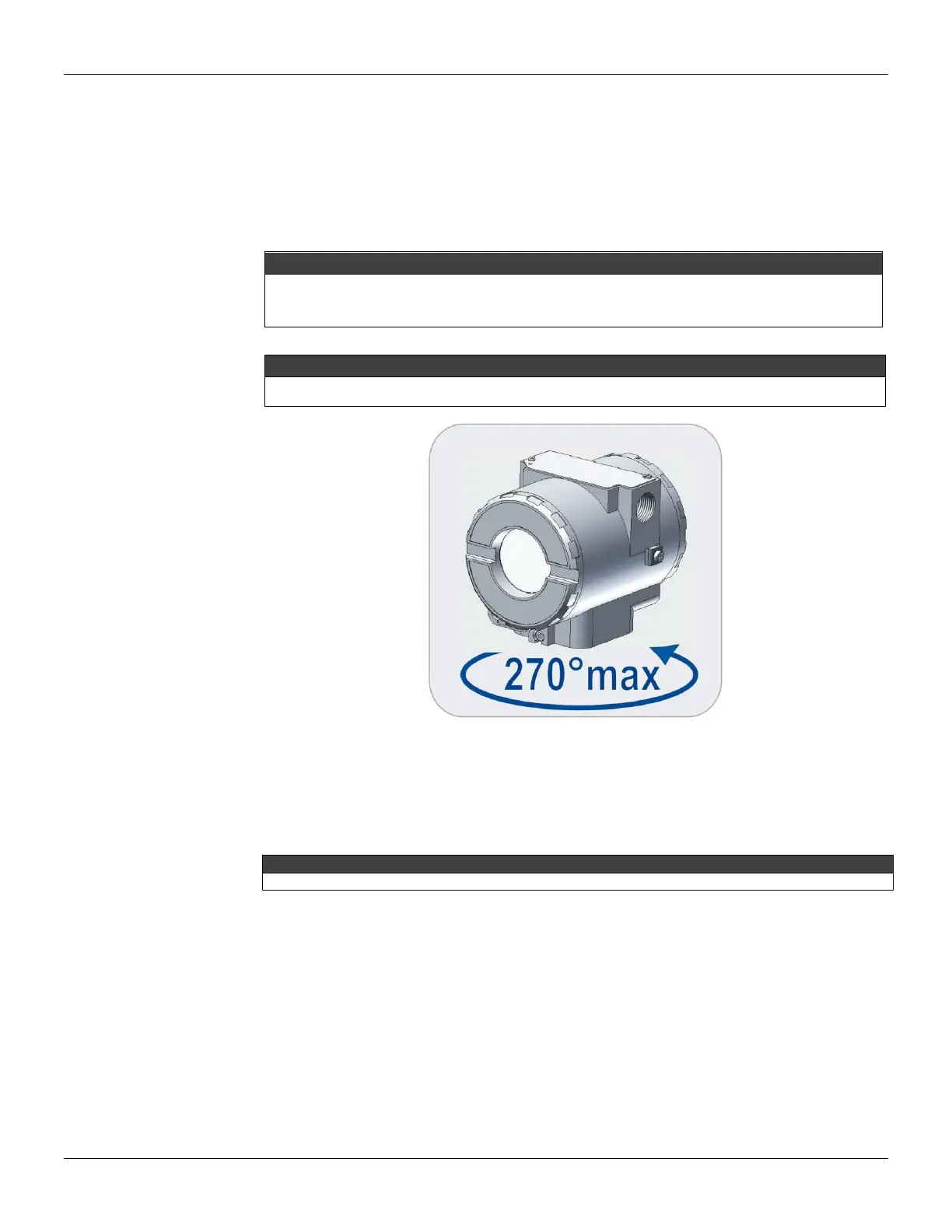
Do not rotate the electronic housing more than 270° without disconnecting the electronic circuit from the power
supply.
Figure 4.1 - Transducer Rotation
Loosen the two screws (3) that anchor the indicator and the main circuit board. Gently pull out the
indicator, and then the main board (5).
Reassembly Procedure
Do not assemble the main board with power on.
Transducer
Mount the transducer to the housing turning clockwise until it stops. Then turn it counterclockwise until it
faces the square of electronic housing to the square of transducer. Tighten the hex screw (6) to lock the
housing to the transducer.
Electronic Circuit
Plug transducer connector and power supply connector to main board (5). Attach the display to the main
board. Observe the four possible mounting positions. The mark indicates up position.