TP301 – Operation, Maintenance and Instructions Manual
4.2
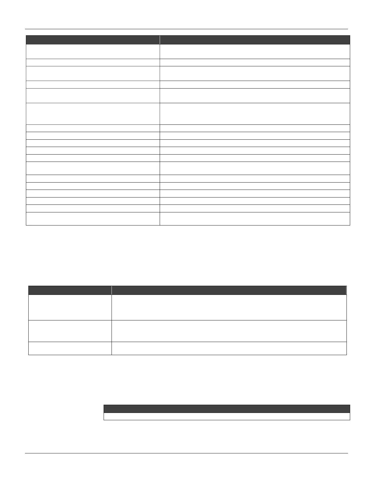
POTENTIAL SOURCE OF PROBLEM
POSITION TRANSMITTER MALFUNCTION
• Transducer disconnected.
• Transducer failure.
• Start-up or reset due to power supply failure.
• Operating in local mode with fix position.
• Connected in burnout.
• Position out of calibrated span or in fail-safe (Output current in 3.9 or 21.0 mA).
• Temperature out of operating limits.
• Temperature sensor damaged.
• Position out of operation transmitter range.
• Transducer damaged or transducer not connected.
• Position transmitter with error configuration.
LOWER RANGE VALUE TOO HIGH
• The lower range value > (Upper limit of range - minimum span).
LOWER RANGE VALUE TOO LOW
• The lower range value < (Upper limit of range).
UPPER RANGE VALUE TOO HIGH
• The upper range value > 110%. (Upper limit of range).
UPPER RANGE VALUE TOO LOW
• The upper range value < -10%. (Lower limit of range).
UPPER AND LOWER RANGE VALUES OUT OF LIMITS
• Both the upper and lower points were outside the transmitter range limit.
• The difference, between the upper and lower points, is less than the allowed by
the transmitter.
• The actual position is above of the upper range limit.
• The actual position is below of the lower range limit.
PASSED PARAMETER TOO LARGE
• Parameter above operating limits.
PASSED PARAMETER TOO SMALL
• Parameter below operating limits.
CONTROL LOOP SHOULD BE IN MANUAL
• Indicates the operation could affect the output.
CONTROL LOOP MAY BE RETURNED TO AUTO
• After the operation is completed, you are reminded to return the loop to automatic
control.
Table 4.1 - TP301 Diagnostics with Configurator
Diagnostics without Configurator
ERROR MESSAGES
The Table 4.2 presents a list of possible diagnosis for the TP301.
When the Indicator presents FAIL, the output current 3.6 mA, the default value for FAIL
SAFE configuration.
If the position may be either below or above the limits. Check if the magnet this installed
correctly.
The configurator allows the user to configure FAIL, the value of the current, 3.6 mA or
21 mA, it is defined in agreement with FAIL SAFE chosen: Up or Down.
Verify electrical connection between the circuit boards.
NO OUTPUT SIGNAL
VARIATION
Verify if the Magnet it is not stuck or loosen.
Table 4.2 - TP301 Diagnostics without Configurator
Disassembly Procedure
Refer to TP301 Exploded View figure (Figure 4.3). Make sure to disconnect power supply before
disassembling the position transmitter.
The numbers indicated between parentheses refer to Figure 4.3 – Exploded View.