Installation
1.7
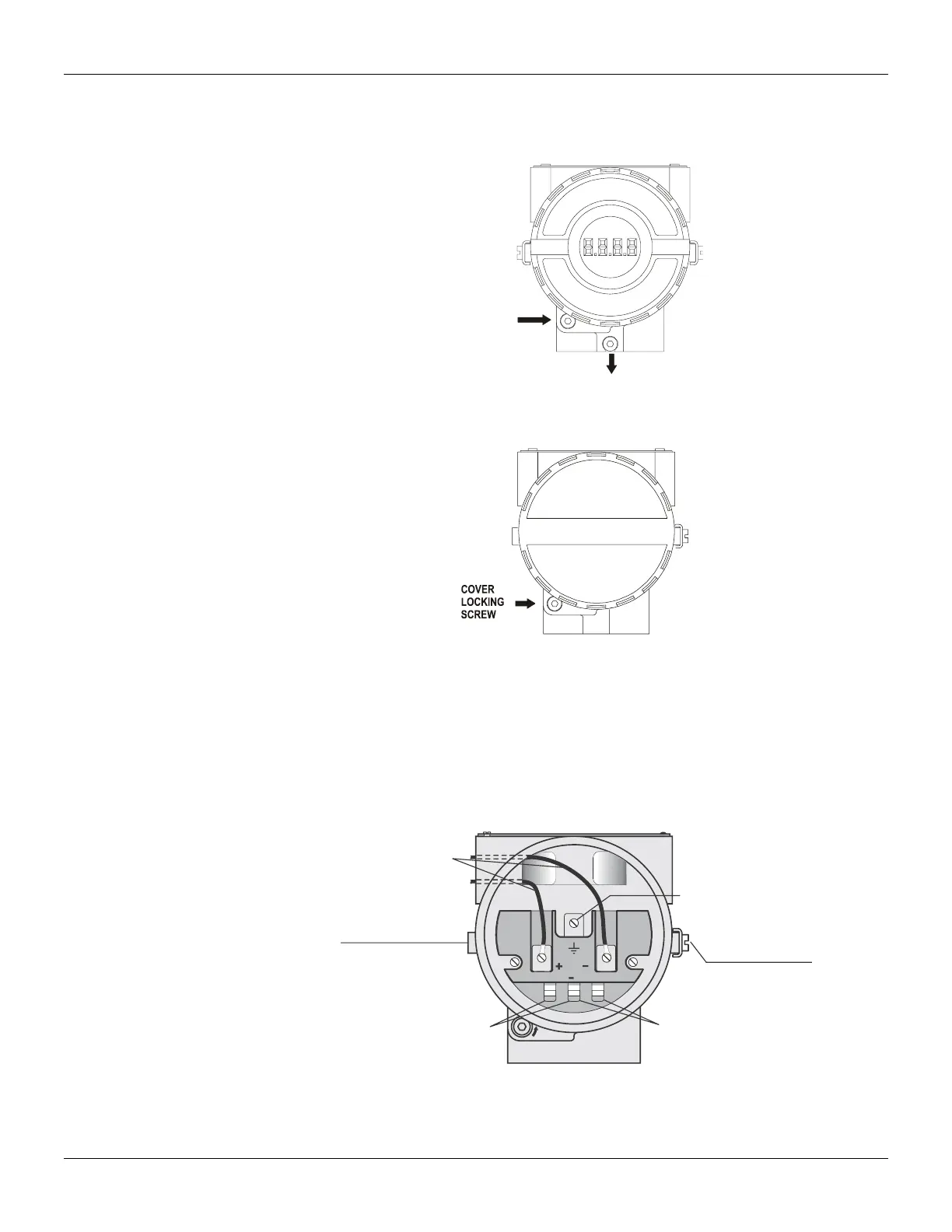
Electronic Housing Rotating
The electronic housing rotates for a better digital display reading. To rotate it, release the housing
rotation screw.
Figure 1.6 - Cover Locking and Housing Rotation Set Screw
Figure 1.7 - Cover Locking Screw
Electric Wiring
The digital display also rotates for better reading. It is necessary to release the electronic house
front cover (release de cover locking screw), release the electronic circuit board screws and choose
one of the 90º different positions. Reassembly the whole set. To access the terminal block for
electronic connections, remove the cover locking screw.
The terminal block accepts forks or eye-type connectors. For convenience there are two ground
terminals: one inside the cover and one external, located close to the conduit entries.
Figure 1.8 - Wiring Block
Use of twisted pair (22 AWG or greater than) cables is recommended. Avoid routing signal wiring
cables close to power cables or switching equipment.