TP301 – Operation, Maintenance and Instructions Manual
1.6
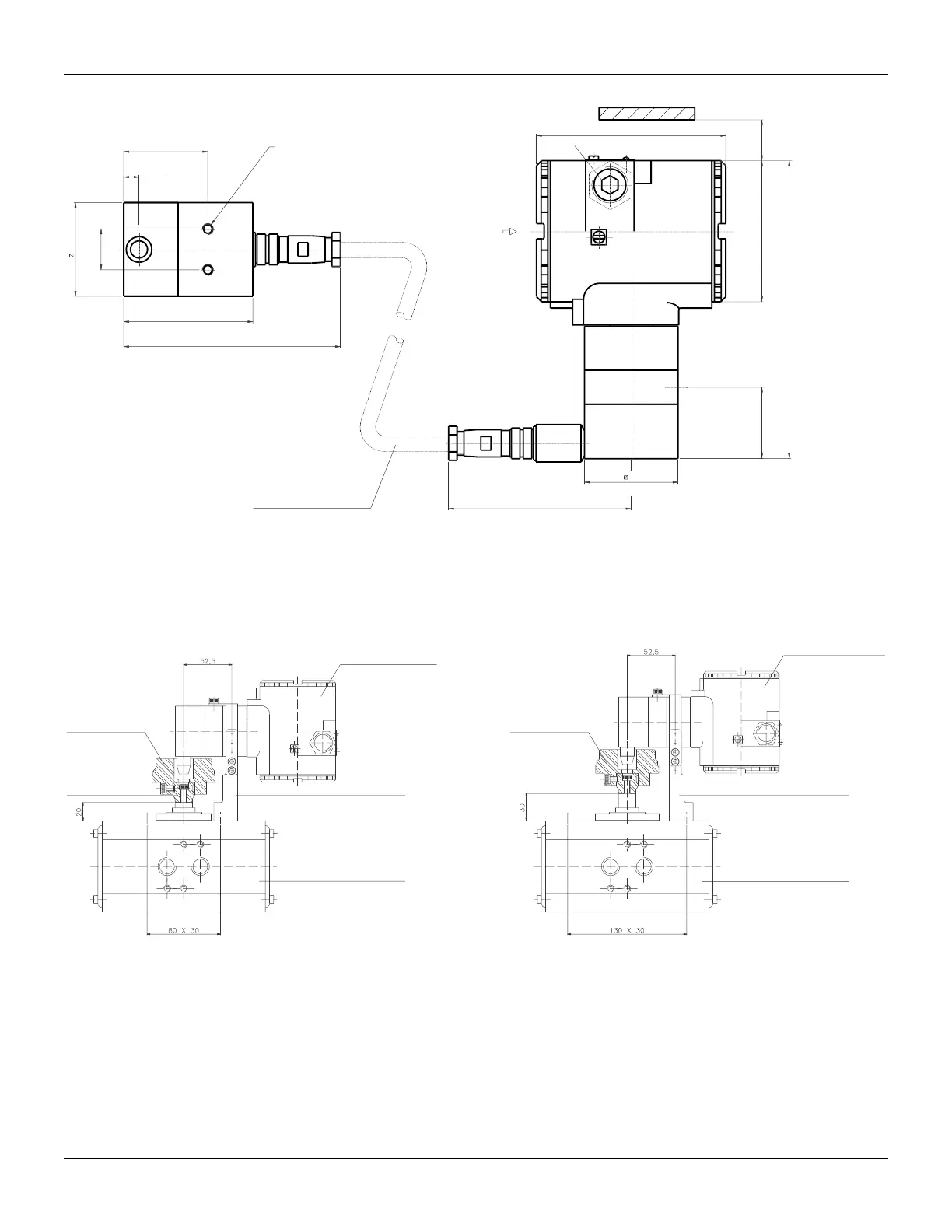
REMOTE SENSOR
83
(3.27)
Leave, at least, a 150 mm space, for
zero and span adjustment with the
magnetic tool.
PLUG
ELECTRICAL
CONNECTION
113
(4.45)
(0.35)
9
(2.16)
55
(6.89)
175
76
49.5
55
(2.17)
THREADS FOR SCREWS
M6 x 1 ( 2 PLACES )
127
107
(4.21)
FLEXIBLE SHIELD CABLE
AVAILABLE LENGHTS:
5 m, 10 m, 15 m, 20 m
(2.99)
(5)
(1.95)
(0.94)
24
42
Figure 1.5.a – Remote Sensor Dimensional Drawing
SPECIAL MOUNTING BRACKET – ROTARY VDI / VDE NAMUR
Mounting bracket of the position transmitter for rotary valves actuated via type actuators rack and
pinion, designed to comply with NAMUR VDI/VDE.
POSITON TRANSMITTER
POSITON TRANSMITTER
ROTARY MAGNET
ROTARY MAGNET
MAGNET BRACKET
MAGNET BRACKET
MOUNTING BRACKET
MOUNTING BRACKET
PNEUMATIC ACTUATOR
NAMUR VDI/VDER STANDARD
PNEUMATIC ACTUATOR
NAMUR VDI/VDER STANDARD
Mounting 80 mm between centers, 20 mm stem
height.
Mounting 130 mm between centers, 30 mm
stem height.
Figure 1.5.b – Special Mounting Bracket Dimensional Drawing - Rotary VDI / VDE NAMUR